.png)
.png)


200X Pressure Reducing Valve
200X Pressure Reducing Valve Purpose
Adjust and control the outlet pressure of the master valve. The said pressure will not be changed along with the change with the inlet pressure, neither along with the change of the flow on the master valve outlet, Applicable for the living water supply, firefighting system and industrial water supply system.
200X Pressure Reducing Valve Principle
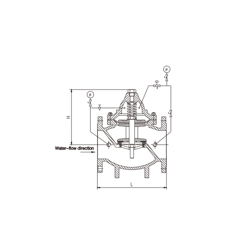
He medium, when enters the lower cavity of the body, pushes the disc upward and, at the same time, the medium enters the upper cavity of the diaphragm via the control pipe outside of the master valve. The upper cavity pressure is adjusted by the pilot valve The pressure difference between the upper and lower cavities decides the up-and-down movement of the disc so as to change the outlet pressure, When the pressures of both cavities are identical, the disc stops at a some position and the outlet pressure is kept unchanged, acting at stabilizing the pressure.
200X Pressure Reducing Valve Definition and Components
What is a 200X Pressure Reducing Valve and its Main Parts?
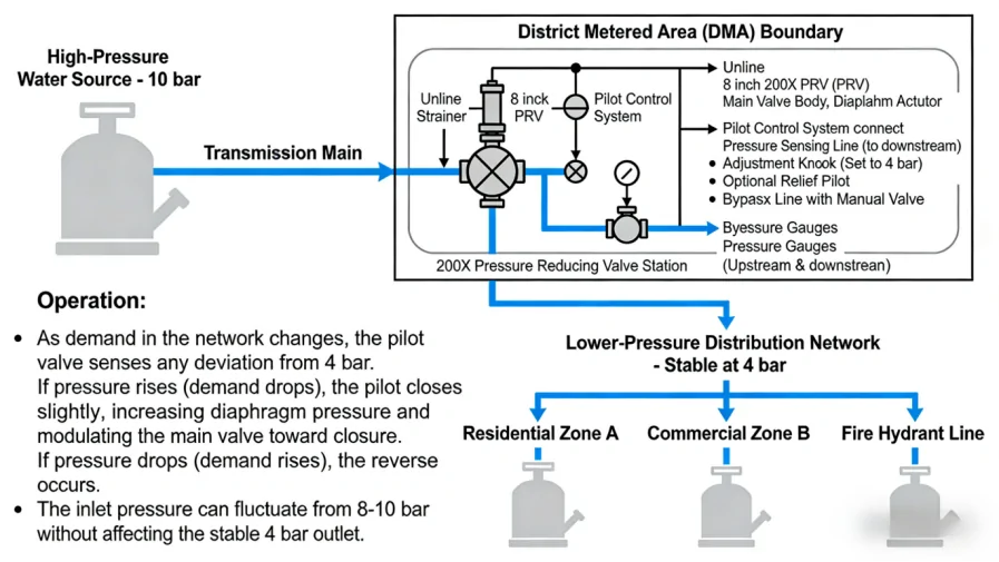
The 200X Pressure Reducing Valve is a pilot-operated, diaphragm-actuated control valve designed to automatically reduce a higher, variable inlet pressure to a stable, lower outlet pressure, regardless of changes in upstream pressure or downstream flow demand. The "200X" designation is a common model series from manufacturers like Bermad, Cla-Val, and OCV, often used in water, fire protection, and industrial applications.
Pressure Reducing Valve Main Components:
- Main Valve Body: Contains the primary flow control element (a globe, angle, or Y-pattern design) with a seat and a movable disc or piston.
- Diaphragm Actuator Chamber: A sealed chamber with a flexible diaphragm. Pressure above the diaphragm controls the main valve's position.
- Control Pilot Valve: The "brain" of the system. It is a small, precision valve that senses the downstream pressure and regulates the pressure in the diaphragm chamber accordingly.
- Sensing Line (Tap): A small tube that feeds the actual downstream pressure to the pilot valve for sensing.
- Adjustment Spring/Knob: Allows for manual setting of the desired downstream pressure.
- Strainer: Protects the small orifices in the pilot valve from debris in the pipeline.
- Optional Solenoid Valve or Check Valve Pilots: Can be added to the pilot system for remote shut-off, pressure relief, or other control functions.
Role, Characteristics, and Application Scenarios of 200X Pressure Reducing Valve in Pipelines
Water Valves Functions, Operational Features, and Usage Scenarios
Functions in Pipelines/Systems:
- Pressure Reduction: Maintains a safe, constant downstream pressure lower than the upstream supply pressure.
- Pressure Sustaining: In certain configurations, it can maintain a minimum upstream pressure by closing.
- Leakage & Break Protection: By limiting downstream pressure, it minimizes water loss and damage from pipe bursts.
- Flow Control: Works in conjunction with pressure reduction to manage system demand.
Operational Features:
- Pilot-Operated for Accuracy: Provides stable, precise control with low hysteresis, superior to direct-acting valves for larger sizes and flows.
- Downstream Pressure Sensing: The control is based on the actual downstream condition, ensuring set-point stability.
- Modulating Action: Opens and closes proportionally to maintain the set pressure, reducing water hammer compared to on/off valves.
- Wide Rangeability: Can handle significant variations in flow rate while maintaining outlet pressure.
- Fail-Safe Modes: Typically fails in the last position or can be specified to fail open/closed depending on the application.
Water Pressure Valve Typical Usage Scenarios:
- Municipal Water Distribution: Reducing high transmission main pressure to lower, safe levels for residential district zones.
- Building Water Supply: Protecting plumbing fixtures and appliances in tall buildings (pressure reduction at floor levels or building inlet).
- Fire Sprinkler Systems: Supplying stable, prescribed pressure to sprinkler risers.
- Industrial Process Lines: Providing consistent feed pressure to sensitive equipment or processes.
- Irrigation Systems: Protecting drip emitters and laterals from high mainline pressure.
200X Pressure Reducing Valve Standards: Materials, Design, and Connections
Material, Design, and Connection Standards
Material Standards:
- Valve Body & Bonnet: Ductile Iron (ASTM A536), Bronze (C84400), Cast Iron (ASTM A126), or Cast Steel (ASTM A216 WCB) for higher pressures. For potable water, certified lead-free materials (e.g., NSF 61).
- Internal Trim (Seat, Disc): Stainless Steel (ASTM A479 Type 316), Brass, or reinforced EPDM/Nitrile.
- Diaphragm: Multiple-ply fabric-reinforced EPDM or Nitrile, suitable for water.
- Pilot Valve Body: Brass or Stainless Steel.
- Springs: Stainless Steel.
Design & Performance Standards:
- General Valve Standards: AWWA C550 (Diaphragm Valves) is highly relevant. API 6D/ASME B16.34 may apply for specific oil & gas applications.
- Face-to-Face Dimensions: Often follows AWWA C509 (Resilient Seated Gate Valves) or ISO 5752.
- Pressure Rating: Class 150, 200, 300 per ASME B16.1/B16.42 (Iron) or B16.5/B16.47 (Flanges).
- Flow & Capacity Testing: Often referenced to ISA 75.01 or manufacturer's CV/KV testing.
Connection Standards:
- Flanged Ends: Predominant. ASME B16.1 Class 125/250 (Iron), ASME B16.5 Class 150/300 (RF flanges). Drilling can be ANSI B16.1 or ISO 7005.
- Mechanical Joint (MJ): Common in waterworks per AWWA C111/A21.11.
- Grooved Ends: Per AWWA C606 for specific applications.
- Threaded Ends: NPT (ASME B1.20.1) for smaller sizes.
How to Select Such Valves
Procurement Process
Define Critical Application Parameters:
- Fluid: Water (potable, raw, sea), type of gas, or mild chemical.
- Pressures: Maximum Inlet Pressure (P1), Required Outlet Pressure (P2) range, and shut-off pressure differential.
- Flow Rates: Minimum, normal, and maximum flow (Qmin, Qn, Qmax).
- Sizing: This is crucial. Provide data to the supplier for CV/KV sizing to avoid cavitation, noise, or poor control.
- Accuracy & Stability: Required +/- % pressure control band.
- Special Needs: Bypass requirement, need for integral pressure gauges/relief, corrosion coating (e.g., epoxy per AWWA C550).
Supplier Selection:
Target specialized control valve or waterworks valve manufacturers (e.g., Bermad, Cla-Val, Watts, Siemens, DeZURIK).
Evaluate their experience in your specific industry (municipal vs. industrial).
Technical Review:
Require detailed sizing calculations and a selection chart showing the valve's operational range relative to your parameters.
Review GA drawings, pilot schematic, and material specification sheets.
Confirm pilot valve configuration (e.g., basic reducing, with relief, with solenoid).
Commercial & Logistics:
Lead times for common sizes (2"-12") are typically 8-16 weeks.
Incoterms and packaging requirements (crated, palletized).
Spare Parts Kit: Essential to include diaphragm kit, pilot repair kit, spare strainer screens, and O-rings.
Support Requirements:
Clear IOM manuals with setup, adjustment, and troubleshooting guides.
Availability of commissioning support or training.
Pre-Shipment Inspection for Export 200X Pressure Reducing Valve and Key Considerations
Pre-Shipment Inspection & Export Precautions
- Inspection & Testing Checklist (Witnessed FAT is Recommended):
- Documentation Review: Verify MTRs for body, trim, and diaphragm. Coating certificates, assembly drawings, and test procedures.
- Visual & Dimensional: Check for proper identification, coating integrity, flange finish/drilling, and overall workmanship.
- Material Verification: Ensure materials match the purchase order (e.g., ductile iron vs. cast iron).
Functional & Performance Tests:
- Shell & Seat Leakage Test: Per AWWA C550 or API 598. The valve is pressurized at 1.5x rated pressure to check body leaks, then at 1.1x rated pressure to check seat tightness (allowable leakage defined by standard).
- Set-Point & Operation Test: Connect the valve to a test loop. Set the desired outlet pressure with the adjustment knob. Vary the inlet pressure and downstream flow while measuring the outlet pressure stability. Verify it maintains the set pressure within the specified accuracy band.
- Strainer Blow-down Test: Verify the strainer can be cleaned/purged.
- Manual Operation Check: If equipped, test any manual override mechanism.
Key Precautions for Export:
- Internal Preservation: The valve and pilot system internals must be thoroughly dried and preserved with a non-corrosive, water-displacing vapor phase inhibitor (VPI) or light oil spray. This is critical to prevent corrosion during sea transit.
- Pilot Protection: The sensitive pilot valve should be removed, preserved separately, and securely packed inside the main valve crate in its own sealed bag with desiccant. Alternatively, the entire pilot assembly can be blocked off and protected.
- Movement Securing: The main valve disc should be mechanically locked or blocked open to prevent damage to the seat and diaphragm from vibration during transport.
- Crating & Protection: Use a robust wooden crate. All external connections (flange faces, pilot ports) must be protected with durable, multi-layer plywood or plastic covers bolted on, not just tape. Use VCI paper and desiccant bags inside the crate.
- Clear Markings: Mark "Pressure Relief Valve," "Keep Dry," "This Side Up," and lifting points clearly on the crate. Include a detailed packing list inside a waterproof pouch attached to the crate.
200X Pressure Reducing Valve Main dimensions(mm)
| DN | Length | Main dimensions | |||||||||
| 1.0MPa | 1.6MPa | 2.5MPa | |||||||||
| mm | L | D | D1 | n-d | D | D1 | n-d | L | D | D1 | n-d |
| 50 | 218 | 160 | 125 | 4-18 | 160 | 125 | 4-18 | 235 | 160 | 125 | 4-19 |
| 65 | 235 | 180 | 145 | 4-18 | 180 | 145 | 4-18 | 240 | 180 | 145 | 8-19 |
| 80 | 250 | 195 | 160 | 8-18 | 195 | 160 | 8-18 | 290 | 195 | 160 | 8-19 |
| 100 | 290 | 220 | 180 | 8-18 | 220 | 180 | 8-18 | 325 | 230 | 190 | 8-23 |
| 125 | 325 | 245 | 210 | 8-18 | 245 | 210 | 8-18 | 340 | 270 | 220 | 8-28 |
| 150 | 360 | 282 | 240 | 8-22 | 282 | 240 | 8-22 | 400 | 300 | 250 | 8-28 |
| 200 | 425 | 335 | 295 | 8-22 | 335 | 295 | 12-22 | 465 | 360 | 310 | 12-28 |
| 250 | 508 | 400 | 350 | 12-22 | 400 | 355 | 12-26 | 555 | 430 | 370 | 12-31 |
| 300 | 590 | 445 | 400 | 12-22 | 460 | 410 | 12-26 | 625 | 485 | 430 | 16-31 |
| 350 | 647 | 505 | 460 | 16-22 | 520 | 470 | 16-26 | ||||
| 400 | 720 | 565 | 515 | 16-26 | 580 | 525 | 16-30 | ||||
| 450 | 743 | 615 | 565 | 20-26 | 640 | 585 | 20-30 | ||||
| 500 | 782 | 670 | 620 | 20-26 | 715 | 650 | 20-34 | ||||
| 600 | 917 | 780 | 725 | 20-30 | 840 | 770 | 20-36 | ||||
Note:1. Other specifications and flange standards are available upon request.
- Design and specifications are subject to change without prior notice.