


Pressure Gauge
Pressure Gauge Definition and Components
A Pressure Gauge is a mechanical (or electronic) instrument used to measure and visually indicate the pressure of a fluid (liquid or gas) within a closed system, such as a pipeline, vessel, or tank. Its primary purpose is to monitor system health, ensure safe operation, and verify process conditions.
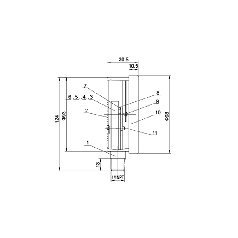
Main Parts of a Bourdon Tube Valve Pressure Gauge (Most Common Type):
1.Case / Housing: The outer protective shell, typically made of stainless steel, plastic, or phenolic. It has a glass or plastic crystal front.
2.Bourdon Tube: The core sensing element. It is a C-shaped, helical, or spiral tube made of metal (e.g., phosphor bronze, 316SS). Pressure causes it to flex/straighten proportionally.
3.Movement (Linkage & Gear Sector): A mechanical assembly that converts the small motion of the Bourdon tube's tip into a large rotary motion of the pointer. It consists of a link, a sector gear, and a pinion gear.
4.Pointer: The needle that moves across the dial to indicate the pressure value.
5.Dial (Scale): The graduated face plate with pressure units (e.g., psi, bar, kPa). It includes the range and accuracy class.
6.Socket / Connection: The threaded (e.g., NPT, G) or flanged inlet that connects the gauge to the system.
7.Blow-out Disc (Safety Feature): A reverse metal disc on the back of some gauges designed to rupture and safely vent pressure if the Bourdon tube fails, protecting the operator.
Role, Characteristics, and Application Scenarios of Pressure Gauge in Pipelines
Guage Valve Functions in Pipelines:
- Process Monitoring: Indicates real-time pressure for normal operation.
- Safety Assurance: Alerts operators to over-pressure or under-pressure conditions that could indicate blockages, pump failures, or leaks.
- System Control: Provides feedback for automated control systems (e.g., to start/stop pumps).
- Leak Detection: A drop in pressure may signify a leak in the system.
- Performance Verification: Used to check the performance of pumps, compressors, and filters.
Fire Valve Operational Features:
- Measuring Range: The minimum to maximum pressure it can read (e.g., 0-100 psi).
- Accuracy Class: The permissible error as a percentage of the full scale (e.g., ±1.0%).
- Dial Size: Common diameters from 63mm to 150mm
- Connection Thread & Location: Bottom (axial) or back (radial) connection.
- Liquid Filling: Glycerin or silicone oil filling dampens pointer vibration and prevents corrosion of internal parts.
Common Usage Scenarios:
- Pump Discharge/Suction: To monitor pump performance and prevent cavitation.
- Filter Inlet/Outlet: To detect clogging via pressure differential.
- Boiler & Steam Lines: Critical for safety in high-temperature systems.
- Compressed Air Systems: On receivers and distribution headers.Hydraulic Systems: To monitor system pressure for machinery operation.
- Chemical & Process Plants: On reactors, vessels, and distribution pipelines.
Pressure Gauge Standards: Materials, Design, and Connections
Material Standards:
- Case: ASTM A36 (Steel), AISI 304/316 (Stainless Steel).
- Bourdon Tube: ASTM B43 (Phosphor Bronze), ASTM A213 (Stainless Steel), CuNi Alloy.
- Seals: FKM (Viton), NBR (Nitrile) for wetted parts based on fluid compatibility.
- Dial & Pointer: Often aluminum or stainless steel.
Design & Performance Standards:
- ASME B40.100: The primary American standard covering pressure gauge terminology, definitions, safety, dimensions, and performance.
- EN 837-1: The primary European standard for Bourdon tube pressure gauges.
- Accuracy Classes: Defined in above standards (e.g., ASME Grade 1A = ±1%, EN 837 Class 1.0 = ±1%).
- Pressure Safety: Standards like ASME B40.100 specify requirements for blow-out discs.
Connection (Thread) Standards:
- NPT (National Pipe Tapered): Most common in the US. (e.g., 1/4" NPT, 1/2" NPT).
- G (Parallel): Common in Europe and Asia (e.g., G 1/4, G 1/2). Often used with an O-ring seal (BSPP).
- M (Metric): Metric parallel threads (e.g., M20x1.5).
- Flange Connections: For high-pressure or specialized applications (to DIN or ANSI flange standards).
How to Select Pressure Gauge?
Follow this systematic approach:
Define Application Parameters:
- Fluid Media: What is being measured? (e.g., water, oil, steam, aggressive chemical). This dictates wetted materials.
- Operating Pressure Range: Select a gauge where the normal operating pressure is at 50-75% of the full scale for best accuracy and longevity.
- Process Temperature: Ambient and fluid temperature affect material selection and may require a syphon or diaphragm seal.
Specify Technical Requirements:
- Accuracy Class: Standard process monitoring (±1.0% to ±1.6%), Critical control (±0.5% or better).
- Dial Size & Readability: Choose based on mounting distance and required visibility.
- Connection Type & Location: NPT or G? Bottom or back connection?
- Case Material & IP Rating: Stainless steel for corrosive/wet environments. Specify Ingress Protection rating (e.g., IP65 for water spray resistance).
- Filling: Glycerin-filled for vibration/pulsation; dry for stable pressure.
Quality & Certification:
- Brand/Manufacturer: Select reputable manufacturers with proven quality.
- Standards Compliance: Confirm conformity to ASME B40.100, EN 837, etc.
- Calibration Certificate: Request a factory test certificate. For critical uses, a 3rd party calibration certificate (traceable to NIST, etc.) may be needed.
Supplier Evaluation:
- Compare technical support, warranty, lead time, and price from multiple suppliers.
- For bulk purchases, request samples for evaluation.
Pre-Shipment Inspection for Export Pressure Gauge and Key Considerations
Inspection Procedure:
Visual Inspection:
- Check for any physical damage to case, crystal, and connection.
- Verify dial markings (range, units, accuracy class) are clear and correct.
- Confirm the model/specification on the nameplate matches the purchase order.
Functional & Calibration Check:
- Zero Point Check: With no pressure applied, the pointer must be at "0."
- Full-Scale Check (If possible): Apply a calibrated pressure source (deadweight tester) at key points (e.g., 25%, 50%, 75%, 100% of range). The indicated reading should be within the stated accuracy class.
- Hysteresis Check: Check that the gauge reads the same value when pressure is increasing and decreasing at the same test point.
Documentation Review:
- Verify the packing list matches the quantity and types of gauges.
- Ensure required certificates (Material Test Report, Calibration Certificate, Compliance Certificate) are included.
Packaging Inspection:
- Ensure each gauge is individually packed in a plastic bag with desiccant (for unfilled gauges).
- Check that the packaging is robust (foam inserts, sturdy carton) to prevent movement and shock during transit.
- The pointer should be restrained (e.g., with a cardboard strip) to prevent damage from bouncing.
Valve Pressure Gauge Material List