


Test & Drain valve
Test & Drain valve Definition and Components
A Test Drain Valve is a specialized multipurpose valve designed for fire protection sprinkler and standpipe systems. Its primary function is to provide a safe, controlled, and metered means to simulate water flow (for alarm and pump activation tests) and to completely drain a section of piping for maintenance, without requiring a full system shutdown.
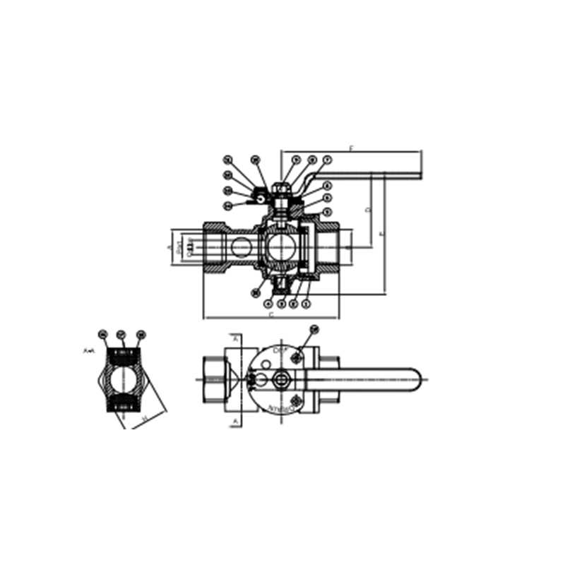
Main Parts (Typical Ball Valve Design):
- Main Valve Body: Houses the primary flow mechanism. Typically a ball valve design for reliable on/off control.
- Ball & Stem Assembly: The rotating ball (with a through-hole) and attached stem that provides quarter-turn operation to open or close the main water flow.
- Drain Port & Valve: A secondary, smaller outlet with its own independent shut-off (often a small gate or ball valve). This is connected to a hose thread for attaching a drain hose.
- Test Port & Valve: A calibrated orifice outlet with its own independent shut-off. This port is sized to simulate the flow of a single sprinkler head. It connects to a test header or hose.
- Inlet & Outlet Connections: Threaded (NPT) or grooved ends for installation into the pipeline.
- Position Indicators: Clearly shows if the main valve is OPEN or CLOSED.
- Operator Handle: Lever for the main valve, often with a padlock provision for lock-out/tag-out safety.
Role, Characteristics, and Application Scenarios of Test & Drain valve in Pipelines
Functions in Pipelines (Fire Protection Systems):
- System Flow Test: The Test Port allows a measured, controlled water discharge to simulate a single activated sprinkler. This verifies the proper operation of water flow alarms (like alarm check valve or vane switch) and automatic fire pump start-up without activating numerous sprinklers.Piping Drainage: The Drain Port provides a full-bore outlet to completely empty a specific section or the entire system of water for winterization, repairs, or modifications.
- Main Flow Control: The main valve isolates the system section for servicing.
Brass Valves Operational Features:
- Sequential Operation: Designed for a safe sequence: Open Main Valve > Open Test Valve for testing > Close Test Valve > Open Drain Valve for full drainage.
- Metered Test Orifice: The test port has a fixed, calibrated orifice (e.g., matching a K-factor of a sprinkler) to ensure accurate flow simulation for alarm tests.
- Hose Thread Connections: Standard NH or NST threads (e.g., 1.5" hose thread on drain, 0.5" on test) for connecting hoses to route water safely to a drain or outside.
- Rugged Construction: Built to handle stagnant water and occasional operation.
Test & Drain valve Standards: Materials, Design, and Connections
Fire Valves Material Standards:
- Body & Ball: Ductile Iron (ASTM A536) or Bronze (ASTM B62). Stainless Steel (ASTM A351 CF8M) for corrosive environments.
- Trim (Stem, Seats): Stainless Steel (AISI 316/304), Brass.
- Seals: EPDM or Viton seats for compatibility with water and corrosion resistance.
Design & Performance Standards:
- UL 993 / FM 1120: These are the key North American standards for Fire Protection System Test and Drain Valves. They govern design, performance, corrosion resistance, and flow characteristics.
- NFPA 13 & NFPA 25: The installation and testing codes that mandate where and how these valves are used (e.g., orifice size for test connections, drain location requirements).
- Pressure Rating: Standard working pressure of 175 psi or 300 psi is common.
Connection Standards:
- Inlet/Outlet: Threaded (NPT - ANSI B1.20.1) or Grooved (AWWA C606) for pipe connections. Sizes typically range from 1" to 4".
- Drain/Test Ports: Standard National Standard Thread (NST) or National Hose (NH) threads, commonly 1.5" NST for drain, 0.5" or 0.75" NST for test port.
How to Select Test & Drain valve?
Follow this purchasing guide: Define System Parameters:
- System Type: Wet pipe, dry pipe, standpipe?
- Application: Main drain, inspector's test, floor control?
- Pipe Size & Connection: Determine the required inlet/outlet size (e.g., 2" NPT) and the hose thread sizes (per NFPA code or system design).Pressure Rating: Match to system design pressure (e.g., 175 PSI).
Specify Compliance & Materials:
- Mandatory Certification: The valve MUST be UL Listed (UL 993) or FM Approved (FM 1120) for fire protection use. This is non-negotiable.
- Material Specification: Request ductile iron body with stainless steel trim and EPDM seals as a robust, standard specification.
- Orifice Size: Confirm the test orifice K-factor (e.g., K=5.6) matches your system's design requirements for alarm testing.
Supplier & Logistics:
- Source from reputable fire protection equipment distributors or direct from certified manufacturers (e.g., Victaulic, Tyco, Mueller).
- Request product data sheets and the UL/FM listing card for the specific model.
- Compare lead times. These are often stock items, but custom configurations may have delays.
Pre-Shipment Inspection for Export Test & Drain valve and Key Considerations
Inspection Procedure:Visual & Dimensional Check:
- No casting defects, cracks, or heavy tool marks on the body.
- All handles operate smoothly without binding.
- Verify thread types and sizes (pipe threads and hose threads) with gauges.
- Check for clear, permanent marking of model, size, pressure rating, and manufacturer.
Functional & Pressure Test (Crucial):
Shell Test: The factory must hydrostatically pressure test the closed main valve body to 1.5x its rated working pressure for a duration (per UL/FM standards). Ensure a test certificate is provided.Seat Test: A test for leakage past the closed main valve seats at rated pressure.Operational Check: Cycle all valves (Main, Test, Drain) from fully open to fully closed to ensure smooth operation.
Documentation & Packaging Check:
- Verify UL/FM Certification Mark is physically on the valve.Ensure packing list includes all accessories (e.g., pipe plugs for unused ports).
- Valves should be individually packaged to prevent damage. Threads must be protected with sturdy plastic caps (not tape).
- All internal passages should be dry and free of oil/grease to protect the fire system water supply.
Test & Drain valve Chart