


Angle Hose Valve F&M
Angle Hose Valve F&M Definition and Components
An Angle Hose Valve (F & M) is a specialized quarter-turn ball valve designed for fire protection standpipe and hose systems. The "Angle" refers to its 90-degree body configuration, where the outlet is perpendicular to the inlet. "F & M" denotes the thread types: "F" for Female (internal) pipe thread at the inlet, and "M" for Male (external) hose thread at the outlet. It serves as a controlled connection point for a fire hose.
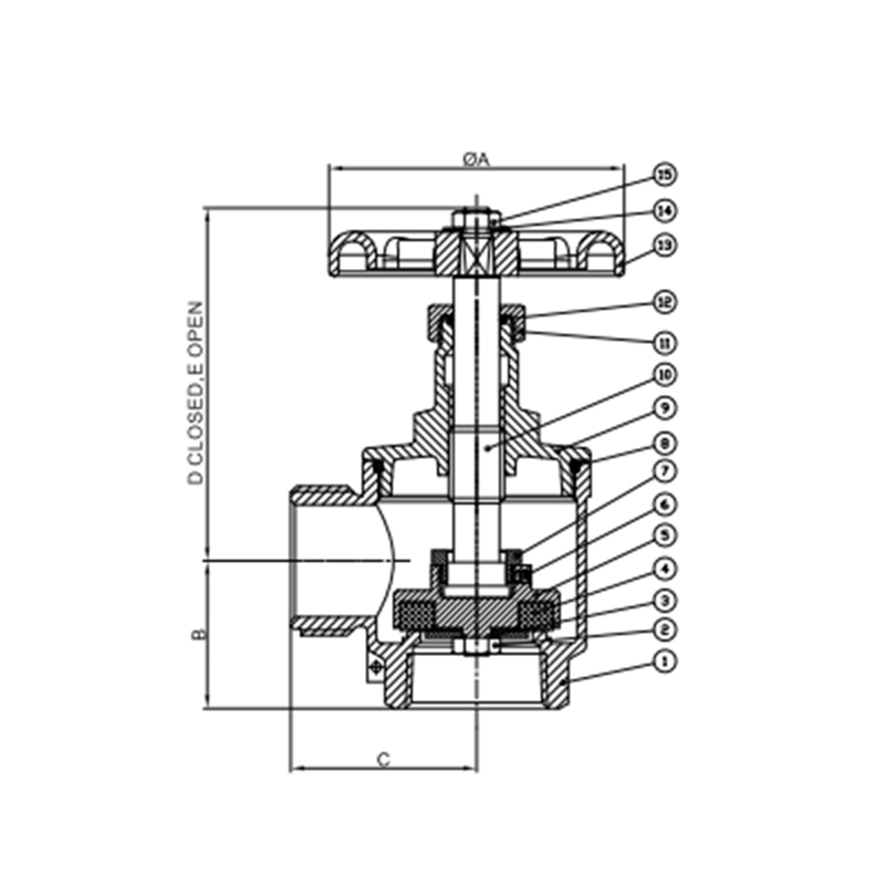
Main Parts:
- Angled Body: Ductile iron or bronze casting forming a 90-degree flow path.
- Ball & Stem Assembly: Chrome-plated brass or stainless steel ball with a through-hole, connected to the operating stem.
- Quick-Open/Close Handle: Lever for quarter-turn operation, often with a padlock provision.
- Inlet Connection (F): Female pipe thread (e.g., NPT) to connect to the standpipe.
- Outlet Connection (M): Male fire hose thread (e.g., NST) to connect the fire hose.
- Seats & Seals: Resilient EPDM or PTFE seals for tight shut-off.
Role, Characteristics, and Application Scenarios of Angle Hose Valve F&M in Pipelines
Fire Valves Functions in Pipelines:
- Hose Connection Point: Provides a dedicated, valved outlet for a fire hose on a standpipe system.
- Flow Control: Allows firefighters to quickly start, stop, and regulate water flow to the attached hose.
- System Isolation: Isolates the hose line from the standpipe main for maintenance.
- Freeze Protection: The automatic drain empties the valve body when closed to prevent water accumulation and freezing.
Operational Features:
- Quarter-Turn Operation: Lever allows for fast, full-open or full-close action.
- Hose Thread Outlet: Standardized male fire department thread (e.g., 1.5" NST).
- Automatic Drain: A small hole or channel that drains water from the valve body cavity upon closure.
- Pressure Rating: Typically 175 psi or higher for fire service.
Common Scenarios:
- Building Standpipes: Installed on each floor's hose cabinet or hose rack.
- Industrial Fire Lines: On wet or dry standpipe systems in warehouses and factories.
- Fire Department Connection (FDC): As the valve on the siamese connection's outlet.
- Scenario Diagram: Typical Installation on a Standpipe
Angle Hose Valve F&M Standards: Materials, Design, and Connections
Material Standards:
- Body: ASTM A536 (Ductile Iron) or ASTM B62 (Bronze). Exterior epoxy coated.
- Internals (Ball, Stem): ASTM A276 Type 316 Stainless Steel or chrome-plated brass.
- Seats/Seals: EPDM (standard) or Viton for chemical resistance.
Design & Performance Standards:
- UL 668 / FM 1311: Standard for Fire Department Hose Valves. Governs design, performance, endurance, and fire resistance.
- NFPA 14: Standard for the Installation of Standpipe and Hose Systems. Dictates installation requirements.
- Hydrostatic Test Pressure: Typically 2x or 3x the working pressure.
Connection Standards:
- Inlet (Female - F): NPT (National Pipe Tapered) thread per ANSI/ASME B1.20.1. Common sizes: 1.5", 2.0", 2.5".
- Outlet (Male - M): NST (National Standard Thread) or NH (National Hose) fire hose thread per NFPA 1963. Common sizes: 1.5" or 2.5".
How to Select Such Valves?
Follow this purchasing guide:
Define Specifications:
- Size & Threads: Inlet pipe size (e.g., 2" NPT Female) and outlet hose size/thread (e.g., 1.5" NST Male).
- Pressure Rating: Match standpipe system design pressure (e.g., 175 PSI WP).
- Material: Specify Ductile Iron body with epoxy coat and stainless trim.
Verify Mandatory Certifications:
- The valve MUST be UL Listed (UL 668) or FM Approved (FM 1311). Request the listing card.
- Confirm compliance with local fire codes (e.g., NFPA 14, IBC).
Brass Valves Supplier Selection:
- Source from reputable fire protection or industrial valve suppliers.
- Compare pricing from different brands (e.g., Potter, Akron, Naffco, local manufacturers).
- Request a sample or CAD drawing for approval on critical projects.
Pre-Shipment Inspection for Export Angle Hose Valve F&M and Key Considerations
Inspection Procedure:
Visual & Dimensional Check:
- No cracks, porosity, or defects in casting. Coating is even and intact.
- Handle operates smoothly (90-degree stop). No excessive play.
- Verify thread types and sizes with ring/plug gauges. Ensure threads are clean and undamaged.
- Check for permanent marking: Brand, Model, Size, Pressure Rating, UL/FM mark.
Functional & Pressure Test:
- Shell & Seat Test: Confirm factory hydrostatic pressure test certificate is provided (e.g., tested at 500 PSI for a 175 PSI valve).
- Drain Function: With valve closed, verify the automatic drain port is open and unobstructed.
- Operation: Cycle the valve open/close several times. Action must be smooth.
Packaging & Documentation:
- Thread Protection: Both inlet and outlet threads must have heavy-duty plastic caps securely threaded on.
- Internal Protection: Valve interior should be clean, dry, and free of oil/grease.
- Packaging: Individual carton with foam or cardboard inserts to prevent movement.
- Documents: Packing list, test certificate, and UL/FM listing documents must be included in the shipment.