


500X Pressure Relief Valve
500X Pressure Relief Valve Purpose
This Types of Pressure Relief Valves is used for the high building fire fighting system. When the pressure in the water supply pipeline is over the one set for pressure relieving, the pressure relieving valve is opened to prevent both pipeline and equipment from getting damaged due to an excessive pressure; and, when the said pressure lowers to the set value, this valve will be closed automatically.
500X Pressure Relief Valve Principle
The inlet side of the master valve is connected to the pilot valve via a control pipe and, when the pressure at the said side is over the one set for the pilot valve, the pilot valve is opened to relieve the pressure in the upper cavity of the diaphragm and the main disc is opened along with, The master valve relieves pressure and, when the pressure lowers to the set one, the pilot valve is closed,so is the master valve.
500X Pressure Relief Valve Definition and Components
What is a 500X Pressure Relief Valve and its Main Parts?
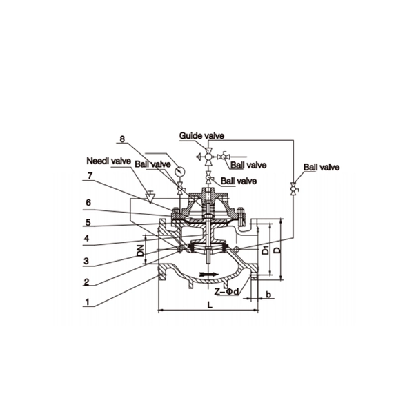
The 500X Pressure Relief Valve is a pilot-operated, modulating pressure relief valve. Its primary function is to automatically open to discharge excess fluid when system pressure exceeds a pre-set limit, and to re-close tightly once normal pressure is restored. The "500X" is a common model series from manufacturers like Bermad, Cla-Val, and others, designed for precise, high-capacity overpressure protection.
Water Valves Main Components:
- Main Valve Body: A normally closed valve (globe or angle pattern) housing the main seat and disc. It opens when pressure in the dome above the diaphragm is released.
- Dome & Diaphragm Assembly: A sealed chamber above the main valve piston/disc. System pressure is fed to the top of this diaphragm via the pilot valve, holding the main valve firmly closed. Releasing this pressure allows the main valve to open.
- Control Pilot Valve: The "brain" of the system. It senses system pressure and controls the pressure in the dome. It typically includes:
- Sensing Element: A spring-loaded piston or diaphragm that reacts to upstream pressure.
- Relief Mechanism: A small seat that opens to vent the dome pressure to atmosphere when the set pressure is exceeded.
- Adjustment Spring/Knob: For setting the precise relief pressure.
- Sensing Line: Connects the valve inlet (system pressure) to the pilot valve.
- Optional Features: Solenoid for remote tripping, pressure gauge ports, test valves, and a drip-tight check valve on the outlet to prevent backflow.
Role, Characteristics, and Application Scenarios of 500X Pressure Relief Valve in Pipelines
Functions, Operational Features, and Usage Scenarios
Water Pressure Valve Functions in Pipelines/Systems:
- Overpressure Protection: The core safety function—prevents system pressure from exceeding the Maximum Allowable Working Pressure (MAWP) of pipes, tanks, vessels, and equipment.
- Modulating/Proportional Relief: Opens in proportion to the overpressure, minimizing system disturbances and fluid loss compared to a popping, snap-action valve.
- Bubble-Tight Seal: Provides excellent sealing at normal operating pressures, eliminating fugitive emissions or leakage common in simple spring-loaded valves.
Operational Features:
- Pilot-Operated for Precision & Stability: Allows for accurate set pressure (±1-2%) with minimal simmer or chatter. The set point is not affected by backpressure.
- High Capacity & Large Orifice: The main valve can be sized for very high flow rates, making it suitable for major pipeline relief
- Modulating Action: Opens gradually as pressure rises above set point, and closes gradually as pressure falls, reducing hydraulic shock (water hammer).
- Zero Leakage: The differential area design and pilot control ensure a tight seal up to 98-99% of set pressure.
Typical Usage Scenarios:
- Pump Discharge Headers: Protects pipelines from pressure surges caused by pump start-ups, check valve slam, or sudden shutdowns.
- Storage Tank Inlets: Prevents over-pressurization of atmospheric or low-pressure tanks.
- Fire Water & Sprinkler Systems: Relieves excess pressure created by constant-running fire pumps
- Water Transmission Mains: Protects downstream lower-pressure zones from upstream pressure excursions.
- Industrial Process Lines: Safeguards heat exchangers, filters, and vessels from thermal expansion or block valve closure.

500X Pressure Relief Valve Standards: Materials, Design, and Connections
Material, Design, and Connection Standards
Material Standards:
- Valve Body & Bonnet: Ductile Iron (ASTM A536), Cast Steel (A216 WCB) for higher pressures/critical service, Stainless Steel (A351 CF8M) for corrosive media.
- Internal Trim (Seat, Disc, Stem): Stainless Steel (316 SS), Brass, or hardened alloys for wear resistance.
- Diaphragm: Fabric-reinforced EPDM, Nitrile, or Viton, compatible with the fluid.
- Pilot Valve: Brass or Stainless Steel.
- Springs: Stainless Steel.
Design & Performance Standards:
- Critical Standard: API Standard 520 Part I & II (Sizing, Selection, and Installation of Pressure-relieving Devices) and API 521 (Pressure-relieving and Depressuring Systems). This is the industry benchmark for hydrocarbon/petrochemical.
- General Valve Design: ASME B16.34 (Valve Pressure-Temperature Ratings).
- Capacity Certification: Often requires ASME BPVC Section VIII certification (UV Stamp) for valves protecting pressure vessels. Capacity must be verified per API 520 or ISO 4126.
- Waterworks: AWWA C510 (for potable water air release/vacuum/combination valves has some relevance, but relief is distinct).
Connection Standards:
- Flanged Ends: Standard. ASME B16.5 Class 150, 300, or 600. RF (Raised Face) or RTJ (Ring Type Joint) facings.
- Inlet/Outlet Sizing: Outlet is often one or two sizes larger than the inlet to minimize backpressure during discharge.
- Pilot Tubing: Small-bore stainless steel or copper tubing with compression fittings
How to Select 500X Pressure Relief Valve
Procurement Process
Define Critical Application Data (Sizing is Paramount):
- Fluid & Properties: Water, oil, gas, steam? Specific gravity, viscosity, compressibility.
- Relief Scenario & Required Capacity: Define the credible overpressure event (e.g., blocked outlet, thermal expansion, fire case). Calculate the Required Relief Rate (kg/hr or m³/hr) using standards like API 520/521 or ISO 4126.
- Pressures: Set Pressure (P_set), Maximum Allowable Working Pressure (MAWP), Accumulation (% over MAWP allowed), Backpressure on valve outlet (superimposed & built-up).
- Sizing: Provide all data to the manufacturer. They must provide sizing calculations to confirm the selected valve orifice area meets the required capacity.
Supplier Selection:
Choose manufacturers with proven expertise in safety relief valves, not just general control valves. They must have in-house engineering for sizing.
Demand references in similar services (e.g., crude oil pipeline protection, produced water surge relief).
Technical Review:
Mandatory: Review and approve the relief valve sizing calculation report.
Review datasheets, GA drawings, and the P&ID of the pilot system.
Confirm materials are compatible with the fluid, especially the diaphragm and seals.
Commercial & Logistics:
Lead times for engineered relief valves are long (18-30 weeks).
Define Incoterms clearly. These are heavy, critical items.
Spare Parts Kit: Must include a complete diaphragm/piston seal kit, pilot valve repair kit, spare sensing line filters, and full set of gaskets.
Support Requirements:
Detailed IOM manual with setup, testing, and troubleshooting procedures.
Availability of certified technicians for commissioning and periodic testing is highly recommended.
Pre-Shipment Inspection for Export 500X Pressure Relief Valve and Key Considerations
Pre-Shipment Inspection & Export Precautions
- Inspection & Testing Checklist (A Witnessed FAT is ESSENTIAL for Safety Valves):
- Documentation Review: Verify ASME/API certification documents, MTRs for all pressure-containing parts, approved sizing calculations, and detailed test procedures.
- Visual & Dimensional: Check nameplate data against purchase order (set pressure, orifice size, materials). Verify flange ratings and finishes.
Critical Functional Tests:
- Shell Test: Hydrostatically test the main valve body at 1.5x design pressure.
- Set Pressure & Seat Tightness Test: This is the core test. The valve is installed on a test bench. Pressure is gradually increased until the valve cracks open (initial lift). This must occur within +/-3% of the specified set pressure. It is then allowed to reach full lift and discharge. Pressure is then decreased until the valve reseats. The reseat pressure is recorded. Finally, a seat leakage test is performed at a specified test pressure (e.g., 90% of set pressure) to confirm bubble-tight sealing per API 527 or FCI 70-2.
- Pilot Valve Function Test: Verify the pilot valve operates smoothly and without chatter.
Key Precautions for Export:
- Internal Preservation: The valve interior and pilot system must be meticulously cleaned, dried, and preserved with a high-quality VPI (Vapor Phase Inhibitor) or approved light oil. Any moisture will cause corrosion during transit.
- Pilot Valve Protection: The precision pilot valve should be removed, individually preserved, and packed separately in a sealed, shock-absorbing container within the main crate.
- Mechanical Locking: The main valve must be secured in the closed position using manufacturer-supplied shipping braces or locks to prevent movement of the piston/disc during transport, which could damage the seat.
- Flange & Port Protection: Use heavy-duty, bolted-on plastic or metal covers for flange faces. All threaded ports must be plugged with solid metal plugs (not plastic).
- Specialized Crating: Use a custom, sturdy wooden crate with internal blocking to immobilize the heavy valve body. Include ample desiccant (silica gel) bags and VCI paper inside.
- Clear Documentation: Mark the crate with "PRESSURE RELIEF VALVE," "SENSITIVE INSTRUMENT," "KEEP DRY," "DO NOT DROP," and lifting points. Include a waterproof pouch containing two copies of test reports, manuals, and packing list attached to the crate.
500X Pressure Relief Valve Main dimensions(mm)
| DN | Length | Main dimensions | |||||||||
| 1.0MPa | 1.6MPa | 2.5MPa | |||||||||
| mm | L | D | D1 | n -d | D | D1 | n -d | L | D | D1 | n -d |
| 50 | 218 | 160 | 125 | 4-18 | 160 | 125 | 4-18 | 235 | 160 | 125 | 4-19 |
| 65 | 235 | 180 | 145 | 4-18 | 180 | 145 | 4-18 | 240 | 180 | 145 | 8-19 |
| 80 | 250 | 195 | 160 | 8-18 | 195 | 160 | 8-18 | 290 | 195 | 160 | 8-19 |
| 100 | 290 | 220 | 180 | 8-18 | 220 | 180 | 8-18 | 325 | 230 | 190 | 8-23 |
| 125 | 325 | 245 | 210 | 8-18 | 245 | 210 | 8-18 | 340 | 270 | 220 | 8-28 |
| 150 | 360 | 282 | 240 | 8-22 | 282 | 240 | 8-22 | 400 | 300 | 250 | 8-28 |
| 200 | 425 | 335 | 295 | 8-22 | 335 | 295 | 12-22 | 465 | 360 | 310 | 12-28 |
| 250 | 508 | 400 | 350 | 12-22 | 400 | 355 | 12-26 | 555 | 430 | 370 | 12-31 |
| 300 | 590 | 445 | 400 | 12-22 | 460 | 410 | 12-26 | 625 | 485 | 430 | 16-31 |
| 350 | 647 | 505 | 460 | 16-22 | 520 | 470 | 16-26 | ||||
| 400 | 720 | 565 | 515 | 16-26 | 580 | 525 | 16-30 | ||||
| 450 | 743 | 615 | 565 | 20-26 | 640 | 585 | 20-30 | ||||
| 500 | 782 | 670 | 620 | 20-26 | 715 | 650 | 20-34 | ||||
| 600 | 917 | 780 | 725 | 20-30 | 840 | 770 | 20-36 | ||||
Note:1. Other specifications and flange standards are available upon request.
- Design and specifications are subject to change without prior notice.