


Socket Ends Gate Valve Z65X
Socket Ends Gate Valve Z65X Definition and Components
1.1 What is a Z65X Socket Ends Non-Rising Resilient Gate Valve?
Z65X is a specialized gate valve designed for direct connection to plastic piping systems without flanges or mechanical joints:
- Z: Gate Valve
- 6: Socket Ends (for solvent welding or mechanical joint to plastic pipes)
- 5: Non-rising Stem (NRS) design
- X: Resilient (Rubber) Seat
This fire protection water supply features integral socket ends designed to accept the insertion of plastic pipes (PVC, HDPE, PP, etc.) for solvent welding, electrofusion, or mechanical joining methods. It's specifically engineered for plastic piping systems in water distribution, irrigation, and industrial applications.
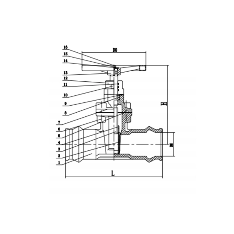
1.2 Main Components (Socket End Specific)
| Component | Socket-Specific Features | Materials |
| 1. Valve Body with Socket Ends | Integral female sockets with depth marks and chamfered entry; designed for specific pipe materials | Ductile Iron, Cast Iron, Bronze, or engineered plastics |
| 2. Resilient Gate | Full rubber encapsulation compatible with plastic pipe systems | EPDM, NBR, or FKM rubber (NSF/ANSI 61 certified) |
| 3. Non-rising Stem | Compact design for limited space installations | 304/316 Stainless Steel |
| 4. Socket Connection System | • Solvent-weld sockets with cement reservoir | Socket dimensions match pipe OD standards |
| • Electrofusion collars (optional) | ||
| • Mechanical restraint clips | ||
| 5. Depth Marks | Clear markings for proper pipe insertion | Engraved or raised markings |
| 6. Gland Assembly | Non-adjustable or adjustable packing system | PTFE or braided graphite packing |
| 7. Handwheel | Compact design for socket end valves | Aluminum or ductile iron |
| 8. Coatings | Internal epoxy for corrosion protection | Fusion-bonded epoxy or special coatings |
Role, Characteristics, and Application Scenarios of Socket Ends Gate Valve Z65X in Pipelines
2.1 Pipeline Functions
- Direct Plastic Pipe Connection: Eliminates transition fittings between plastic and metal
- Isolation in Plastic Systems: Primary shutoff in PVC/HDPE pipelines
- Space-Saving Installation: Compact design ideal for confined spaces
- Corrosion Resistance: Compatible with aggressive water chemistries
- Low Pressure Applications: Typically for pressures up to 150 psi
2.2 Socket-Specific Operational Features
| Feature | Socket End Advantage | Operational Benefit |
| Direct Connection | No flanges or adapters required | Reduced installation time and cost |
| Leak-Free Joints | Solvent-welded or fused connections | Permanent, maintenance-free joints |
| Compact Design | Shorter face-to-face dimensions | Fits in tight spaces |
| Lightweight | Compared to flanged counterparts | Easier handling and installation |
| Corrosion Resistance | Compatible with plastic pipe chemistry | Ideal for aggressive water or chemicals |
| Thermal Compatibility | Matches plastic pipe expansion rates | Reduces stress at connection points |
2.3Typical Socket End Gate Valve for Water Applications:
| Application | Pipe Material | Valve Size | Connection Method |
| Residential Water | PVC Schedule 40 | 3/4" - 2" | Solvent cement |
| Irrigation Systems | PVC Class 200 | 1" - 4" | Solvent cement or threaded |
| Pool & Spa | CPVC or PVC | 1" - 3" | Solvent cement |
| Industrial Process | HDPE, PP, PVDF | 1" - 6" | Butt fusion or electrofusion |
| Chemical Transfer | PVC, CPVC, PP | 1/2" - 3" | Solvent cement or fusion |
Socket Ends Gate Valve Z65X Standards: Materials, Design, and Connections
3.1 Material Standards
| Component | Standards | Materials for Socket Valves |
| Valve Body | ASTM A126 Class B, ASTM B62 | Cast Iron, Bronze, engineered plastics |
| Socket Ends | ASTM D2466, ASTM D2467, ISO 7005 | Sized for specific pipe ODs |
| Gate | ASTM A48 with rubber | Cast iron + EPDM/NBR/Viton |
| Stem | ASTM A276, ASTM B16 | 304SS, 316SS, Bronze |
| Rubber Components | NSF/ANSI 61, FDA 21 CFR 177 | EPDM (water), NBR (oils), FKM (chemicals) |
| Coatings | AWWA C550 (optional) | Epoxy, fusion-bonded coatings |
3.2 Design Standards
| Standard | Title | Socket End Application |
| ASME B16.10 | Face-to-Face Dimensions of Valves | Compact dimensions for socket valves |
| ASME B16.5 | Pipe Flanges and Flanged Fittings | Not typically applicable (socket ends) |
| ISO 7005 | Metallic flanges | Socket dimensions reference |
| ASTM D2466 | Socket-Type Polyvinyl Chloride (PVC) Plastic Pipe Fittings | Socket design for PVC |
| ASTM D2467 | Socket-Type Polyethylene (PE) Plastic Pipe Fittings | Socket design for PE |
| AWWA C500 | Metal-Seated Gate Valves | Design basis (modified for sockets) |
3.3 Connection Standards
Socket End Types and Specifications:
| Socket Type | Standard | Application | Dimensions |
| PVC Socket | ASTM D2466 | Schedule 40/80 PVC | ID matches pipe OD + clearance |
| CPVC Socket | ASTM F438 | Hot water CPVC | Special chamfer for hot service |
| HDPE Socket | ASTM D3261 | Butt fusion ends | Special bevel for fusion |
| Threaded Socket | ASME B1.20.1 | Transition to threaded | NPT female threads |
Socket Dimensions (Example - 2" PVC Socket):
- Socket Inside Diameter: 2.375" (pipe OD + 0.005-0.010 clearance)
- Socket Depth: 1.5" minimum
- Chamfer: 15° internal chamfer
- Cement Reservoir: 0.125" depth
- Depth Mark: Clearly marked at proper insertion depth
How to Select Socket Ends Gate Valve Z65X
4.1 Specification Development Process
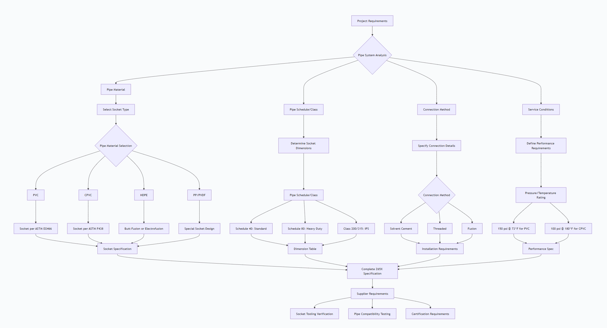
4.2 Critical Socket-Specific Specifications
Socket End Requirements:
SOCKET DIMENSIONAL REQUIREMENTS:
- Standard: Specify exact ASTM standard (e.g., ASTM D2466)
- Pipe Compatibility: Exact pipe OD and material
- Socket Depth: Minimum depth per standard
- Chamfer: Internal chamfer angle and depth
- Cement Reservoir: If for solvent welding
- Depth Marks: Clear, permanent markings
Fire Protection Valves and Fittings Pipe Compatibility Matrix:
| Pipe Material | Valve Body Material | Socket Type | Maximum Pressure |
| PVC Sch 40 | Cast Iron, Bronze | Solvent socket | 150 psi @ 73째F |
| PVC Sch 80 | Cast Iron, Bronze | Solvent socket | 200 psi @ 73째F |
| CPVC | Bronze, engineered plastic | Hot solvent socket | 100 psi @ 180째F |
| HDPE | Ductile Iron, HDPE | Butt fusion | 125 psi @ 73째F |
| PP | Polypropylene | Heat fusion | 100 psi @ 73째F |
Installation Requirements:
- Solvent Cement: Specify cement type (standard, heavy-bodied, etc.)
- Cure Times: Minimum cure time before pressure testing
- Installation Temperature: Range for proper joint formation
- Pipe Preparation: Cleaning and priming requirements
4.3 Supplier Qualification Requirements
Socket-Specific Manufacturing Capabilities:
- Socket Tooling: Proper molds for socket formation
- Dimensional Control: Precision machining of socket IDs
- Material Compatibility: Knowledge of plastic pipe materials
- Testing Facilities: Socket joint pressure testing capability
- Certifications: NSF/ANSI 61, UPC, CSA as required
Factory Audit Checklist for Socket Valves:
Socket Machining: Verify precision and surface finish
- Tooling Maintenance: Check condition of socket molds
- Quality Control: Dimensional verification procedures
- Testing Procedures: Socket joint testing protocols
- Material Traceability: For both valve and socket components
Pre-Shipment Inspection for Export Socket Ends Gate Valve Z65X and Key Considerations
5.1 Socket-Specific Inspection Protocol
Phase 1: Documentation Review
Z65X REQUIRED DOCUMENTS:
- Socket Dimension Certificates (per ASTM standards)
- Pipe Compatibility Certifications
- Solvent Cement Compatibility Reports
- Material Certificates for all components
- NSF/ANSI 61 Certification (for potable water)
- Pressure Test Certificates
- Installation Instructions (socket-specific)
Phase 2: Socket Dimensional Inspection
| Inspection Item | Requirement | Measurement Method |
| Socket ID | Pipe OD + 0.005-0.010 clearance | Internal micrometers |
| Socket Depth | Per applicable standard | Depth gauge |
| Chamfer Angle | 15° ± 2° (typical) | Chamfer gauge |
| Depth Marks | Clear, legible, at correct depth | Visual, measurement |
| Surface Finish | Smooth, free of defects | Visual, surface comparator |
| Cement Reservoir | Properly formed (if applicable) | Depth measurement |
Phase 3: Material Verification
- PMI Testing: Verify body and stem materials
- Rubber Analysis: Verify elastomer type (EPDM, NBR, etc.)
- Coating Inspection: Internal coating integrity
- Socket Material: Verify compatibility with pipe material
Phase 4: Socket Joint Testing
Assembly Test (if possible):
Test Procedure:
- Prepare test pipe per specifications
- Assemble valve to pipe using specified method
- Allow proper cure time (if solvent weld)
- Perform hydrostatic test at 1.5× rated pressure
- Check for leakage at socket joint
Valve Pressure Testing:
- Shell Test: 1.5× rated pressure for 2 minutes
- Seat Test: Rated pressure, zero leakage
- Socket Integrity: Visual inspection after testing
Functional Testing:
- Operation Test: Full open/close cycles
- Torque Measurement: Verify within specifications
- Stem Seal Test: Check for leakage
5.2 Special Socket Considerations
Socket Surface Preparation:
- Verify socket interior is clean and free of contaminants
- Check for proper surface texture for bonding
- Ensure no oil or release agents on socket surfaces
Solvent Cement Compatibility:
- Verify valve manufacturer recommends specific cement types
- Check for compatibility with different cement formulations
- Ensure no chemical incompatibility between socket material and cement
Installation Kit Verification:
- If supplied, check installation tools are included
- Verify instructions are clear and complete
- Check cement/primers are within shelf life
5.3 Export Preparation Protocol
Socket End Protection:
CRITICAL SOCKET PROTECTION:
- Socket Interior: Plastic plugs or caps
- Thread Protection: If threaded sockets, thread protectors
- Surface Protection: Prevent scratches on socket surfaces
- Cleaning: Ensure sockets are clean and dry
- Moisture Control: Desiccant in sockets if prone to corrosion
Packaging Configuration:
- Individual Valve: Each valve in separate carton or crate
- Socket Protection: Rigid caps that won't damage socket surfaces
- Accessory Packaging: Separate packages for installation kits
- Documentation: Waterproof pouch attached to valve
Socket-Specific Marking:
Crate Marking:
- SOCKET END GATE VALVE
- SIZE: [Pipe Size]
- MATERIAL: [Body Material]
- SOCKET TYPE: [e.g., PVC Solvent]
- PRESSURE RATING: [psi @ temperature]
- COMPATIBLE PIPE: [e.g., PVC Sch 40]
Valve Body Marking:
- Size (NPS and metric)
- Pressure rating
- Socket type
- Material designation
- Direction of flow (if applicable)
- Manufacturer and date
Documentation Package:
Technical Documents:
- Socket Dimension Drawings: Detailed socket specifications
- Installation Instructions: Step-by-step socket connection guide
- Compatibility Chart: Pipe materials and cements
- Cure Time Tables: For solvent-welded joints
- Pressure-Temperature Ratings: For different services
Certification Documents:
- NSF/ANSI 61 Certificate (potable water)
- Socket Dimension Compliance Certificates
- Material Certificates
- Pressure Test Reports
- Quality Assurance Certificate
5.4 Special Precautions for Socket Valves
Socket Surface Protection:
- Scratch Prevention: Socket surfaces must remain undamaged
- Contamination Prevention: Keep sockets clean and free of debris
- Moisture Protection: Prevent condensation in sockets
Climate Considerations:
- Temperature Extremes: Protect from freezing or excessive heat
- UV Protection: If stored outdoors, protect from sunlight
- Humidity Control: Desiccant in packaging for humid climates
Handling and Storage:
- Stacking: Do not stack heavy items on socket ends
- Orientation: Store valves in horizontal position
- Support: Adequate support to prevent socket deformation
5.5 Final Inspection Checklist
Before Packaging:
- Socket interiors clean and dry
- Socket protectors installed and secure
- All markings clear and legible
- Valve operates smoothly
- Accessories included and identified
- Documentation complete and accurate
Socket-Specific Checks:
- Socket dimensions verified
- Depth marks clear and correct
- Chamfer present and uniform
- No defects in socket surfaces
- Cement reservoir properly formed (if applicable)
- Threads clean and protected (if threaded)
5.6 Common Socket Valve Issues to Prevent
| Potential Issue | Prevention Method | Inspection Method |
| Socket Damage | Rigid protection caps | Visual inspection, dimensional check |
| Contamination | Clean before shipment, sealed caps | Visual inspection, cleanliness test |
| Incorrect Dimensions | Precision machining, proper tooling | Dimensional verification with pipe samples |
| Poor Surface Finish | Proper machining parameters | Surface roughness measurement |
| Missing Depth Marks | Quality control during manufacturing | Visual inspection, measurement |
| Material Incompatibility | Material certification, compatibility testing | Material verification, compatibility reports |
Installation Kit Contents (if supplied):
Solvent cement (proper type and quantity)
Primer (if required)
Cleaning supplies
Application brushes
Installation instructions
Safety equipment (gloves, goggles)
Socket Ends Gate Valve Z65X Main dimensions(mm)
| DN | 50 | 50 | 80 | 100 | 125 | 150 | 200 | 250 | 300 |
| PVCOD | 63 | 63 | 90 | 110 | 140 | 160 | 225 | 280 | 315 |
| L | 250 | 250 | 280 | 300 | 325 | 350 | 400 | 450 | 500 |
| H | 295 | 295 | 330 | 375 | 456 | 545 | 570 | 640 | 790 |
| Do | 160 | 160 | 200 | 200 | 250 | 250 | 320 | 370 | 370 |
Note:1. Other specifications and flange standards are available upon request.
- Design and specifications are subject to change without prior notice.