.png)
.png)


AWWA C509/C515 Non-rising Resilient Gate Valve Z45X
AWWA C509/C515 Non-rising Resilient Gate Valve Z45X Purpose
This AWWA Gate Valve is mounted on various pipelines and used asa bi-way closed circuit equipment for tap water, sewage treatment, metallurgy, petroleum, building, chemical,electric power industries etc
AWWA C509/C515 Non-rising Resilient Gate Valve Z45X Definition and Components
1.1 What is AWWA C509/C515 Non-rising Resilient Gate Valve Z45X?
AWWA C509/C515 Z45X represents a specialized waterworks gate valve designed to American Water Works Association standards:
Z45X: Chinese designation for Non-rising Stem Resilient Seat Gate Valve
AWWA C509: Standard for Resilient-Seated Gate Valves for Water Supply Service (Underground/Submerged Applications)
AWWA C515: Standard for Reduced-Wall, Resilient-Seated Gate Valves for Water Supply Service (Aboveground/Indoor Applications)
These are high-performance water distribution valves specifically engineered for municipal water systems, meeting rigorous AWWA standards for durability, reliability, and public health safety.
1.2 Main Components (AWWA Specific)
| Component | AWWA C509/C515 Requirements | Common Materials |
| 1. Valve Body | Minimum 0.25" wall thickness for ductile iron; pressure-rated for 150 or 200 psi | Ductile Iron (ASTM A536 65-45-12), Gray Iron (ASTM A126 Class B) |
| 2. Resilient Gate | Full encapsulation with rubber, minimum 0.25" thickness; replaceable in some designs | Cast Iron core with EPDM or NBR rubber (NSF/ANSI 61 certified) |
| 3. Non-rising Stem | Stainless steel, minimum 1" diameter for valves 12" and larger; trapezoidal or square threads | Type 316 Stainless Steel (ASTM A276) |
| 4. Stem Nut (Yoke Bushing) | Bronze or equal; designed for 100% valve operation without adjustment | ASTM B584 C83600 or C93200 Bronze |
| 5. AWWA Seat Rings | Integral or replaceable; machined surfaces for rubber-to-metal seal | Ductile Iron with fusion-bonded epoxy coating |
| 6. Stuffing Box | Deep design for multiple packing rings; adjustable gland follower | 6-8 rings of braided packing or chevron-type seals |
| 7. Handwheel/Operator | Minimum two-handwheel diameters; designed for 150 lb-ft maximum operating torque | Ductile Iron, powder-coated |
| 8. Bolting | ASTM A307 Grade B or better; hot-dip galvanized per ASTM A153 | Carbon Steel, galvanized |
| 9. Protective Coatings | Fusion-Bonded Epoxy (FBE) per AWWA C550 for both internal and external surfaces | Epoxy coating, 10-16 mils thickness |
Role, Characteristics, and Application Scenarios of AWWA C509/C515 Non-rising Resilient Gate Valve Z45X in Pipelines
2.1 Water Valves Pipeline Functions in Water Systems
- Main Line Isolation: Primary shutoff for water transmission and distribution lines
- Pressure Zone Separation: Boundary valves between different pressure zones
- Emergency Shutdown: Critical isolation during main breaks or repairs
- System Maintenance: Enable sectional shutdown without affecting entire system
- Flow Control: Limited throttling capability (though not designed for continuous modulation)
2.2 AWWA-Specific Operational Features
| Feature | AWWA C509 (Buried) | AWWA C515 (Aboveground) | Benefit |
| Design Pressure | 150 or 200 psi | 150 or 200 psi | Standardized pressure ratings |
| End Connections | MJ, Flanged, Restrained | Flanged, Threaded | Flexible installation options |
| Stem Extension | Required for buried valves | Standard stem | Accessible operation below grade |
| Coatings | External: FBE or equivalent | Epoxy paint or FBE | Corrosion protection per AWWA C550 |
| Internal: FBE or cement mortar | |||
| Face-to-Face | Per AWWA C509 Table 2 | Per AWWA C515 Table 2 | Standardized dimensions |
| Testing | Hydrostatic at 300 psi (2 rated) | Hydrostatic at 300 psi | Rigorous quality assurance |
Key AWWA Performance Requirements:
- Zero Leakage: Bubble-tight closure in both directions
- Low Torque Operation: Maximum 150 lb-ft handwheel torque for 12" valve
- Cyclic Endurance: 300 complete cycles minimum
- Hydrostatic Strength: 2× rated pressure without failure
- Backpressure Rating: Equal to forward pressure rating
Typical Municipal Water System Applications:
| Application | Valve Type | Size Range | Special Features |
| Transmission Mains | C509 Buried | 16"-48" | MJ ends, 10-20' stem extensions |
| Distribution Mains | C509 Buried | 4"-12" | Valve boxes, 2-piece construction |
| Pump Stations | C515 Aboveground | 8"-24" | Floor stands, position indicators |
| Treatment Plants | C515 Aboveground | 6"-20" | Epoxy coating, lever operators |
| Storage Tanks | C515 Aboveground | 8"-16" | By-pass valves, drainage ports |
| Fire Protection | C509/C515 | 6"-10" | UL/FM approved, indicating stems |
AWWA C509/C515 Non-rising Resilient Gate Valve Z45X Standards: Materials, Design, and Connections
3.1 AWWA Material Standards
| Component | AWWA Standard | Material Specification |
| Body & Bonnet | AWWA C509/C515 | Ductile Iron per ASTM A536 65-45-12 |
| Gate | AWWA C509/C515 | Ductile Iron with rubber encapsulation |
| Stem | AWWA C509/C515 | Stainless Steel Type 316 per ASTM A276 |
| Stem Nut | AWWA C509/C515 | Bronze ASTM B584 C83600 or C93200 |
| Bolts & Nuts | AWWA C509/C515 | ASTM A307 Grade B, galvanized per ASTM A153 |
| Rubber Components | NSF/ANSI 61 | EPDM (most common), NBR, or Viton |
| Coatings | AWWA C550 | Fusion-Bonded Epoxy (FBE), 10-16 mils |
3.2 Design Standards
| Standard | Title | Key Requirements |
| AWWA C509 | Resilient-Seated Gate Valves for Water Supply Service | Design for underground/buried installation |
| AWWA C515 | Reduced-Wall, Resilient-Seated Gate Valves for Water Supply Service | Design for aboveground/indoor installation |
| AWWA C550 | Protective Interior and Exterior Coatings for Valves and Hydrants | Coating requirements for corrosion protection |
| AWWA C111 | Rubber Gasket Joints for Ductile-Iron Pressure Pipe and Fittings | MJ (Mechanical Joint) end requirements |
| AWWA C115 | Flanged Ductile-Iron Pipe with Ductile-Iron or Gray-Iron Threaded Flanges | Flanged end requirements |
| ANSI/AWWA C500 | Metal-Seated Gate Valves for Water Supply Service | Related standard for metal-seated valves |
3.3 Connection Standards
| Connection Type | Standard | Application |
| Mechanical Joint (MJ) | AWWA C111 | Most common for buried water mains |
| Flanged | AWWA C115, ASME B16.1 Class 125 | Pump stations, treatment plants |
| Threaded | ASME B1.20.1 | Smaller sizes (2"-4") for building services |
| Restrained Joint | AWWA C509 Annex A | For thrust restraint without external anchors |
Gate Valve for Water Pressure Ratings:
- Working Pressure: 150 psi (standard) or 200 psi (high pressure)
- Test Pressure: 300 psi (hydrostatic) per AWWA standards
- Surge Pressure: Capable of withstanding 2× working pressure momentarily
How to Select AWWA C509/C515 Non-rising Resilient Gate Valve Z45X
4.1 Specification Development Process
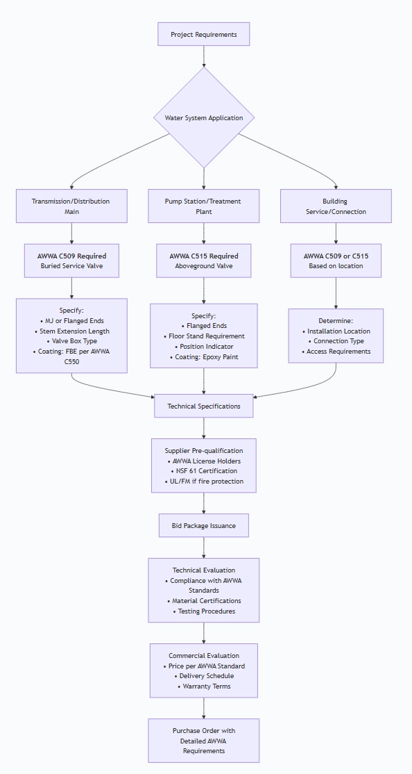
4.2 Critical Specification Elements
- Mandatory AWWA Requirements:
- STANDARD COMPLIANCE:
- Must be manufactured per AWWA C509 or C515
- Must bear AWWA monogram if applicable
- Must include AWWA-certified materials
- MATERIAL REQUIREMENTS:
- Body: Ductile Iron ASTM A536 65-45-12
- Stem: 316 Stainless Steel, minimum diameters per AWWA
- Stem Nut: Bronze C83600 or C93200
- Coating: FBE per AWWA C550 for C509, epoxy paint for C515
- PERFORMANCE REQUIREMENTS:
- Hydrostatic Test: 300 psi for 2 minutes minimum
- Seat Test: Zero leakage at 150 psi (or 200 psi)
- Torque: Not to exceed AWWA maximums
- Cycles: Minimum 300 complete operations
. Size and Connection Specifications:
Valve Size: 4", 6", 8", 10", 12", 16", 20", 24", 30", 36", 42", 48"
End Types:
MJ (AWWA C111) for buried service
Flanged (AWWA C115) for aboveground
Special: Shouldered ends for restrained joints
Operating Nut: 2" square for 12" and larger valves
1.Special Requirements Checklist:
NSF/ANSI 61 Certification for potable water
UL/FM Approval for fire protection service
Stem Extensions (specify length for buried valves)
Valve Boxes (specify type and material)
By-pass Valves (for large diameter valves)
Drain Connections (for pump station valves)
Position Indicators (aboveground valves)
Locking Devices (for security)
4.3 Supplier Qualification Requirements
Mandatory Certifications:
✅ AWWA License: Manufacturer must be licensed to produce C509/C515 valves
✅ ISO 9001: Quality management system certification
✅ NSF/ANSI 61: Certification for potable water contact materials
✅ UL/FM: If valves are for fire protection service
Factory Audit Points:
AWWA standard compliance in manufacturing processes
Quality control and testing facilities
Coating application equipment (FBE application capability)
Material traceability systems
Production capacity and lead times
4.4 Bid Evaluation Criteria
| Criteria | Weight | Evaluation Factors |
| Technical Compliance | 40% | AWWA standard compliance, material certifications, testing procedures |
| Quality & Reputation | 25% | AWWA license status, project references, failure rate history |
| Delivery & Service | 20% | Lead time, technical support, spare parts availability |
| Price Competitiveness | 15% | Total installed cost, warranty terms, lifecycle costs |
Pre-Shipment Inspection for Export AWWA C509/C515 Non-rising Resilient Gate Valve Z45Xand Key Considerations
5.1 AWWA-Specific Inspection Protocol
Phase 1: Documentation Review (AWWA Requirements)
MANDATORY DOCUMENTS:
- AWWA Certification Documents
- Material Test Certificates (per AWWA C509/C515)
- NSF/ANSI 61 Certification for all wetted parts
- Coating Certificates (FBE per AWWA C550)
- Hydrostatic Test Reports (300 psi minimum)
- Dimensional Inspection Reports
- AWWA Compliance Certificate
- Operation and Maintenance Manuals
Phase 2: Visual and Dimensional Inspection
| Inspection Item | AWWA Requirement | Acceptance Criteria |
| Body Markings | Per AWWA C509 Section 8 | Must include: AWWA standard, size, pressure rating, manufacturer, year |
| Coating Thickness | AWWA C550: 10-16 mils | Minimum 10 mils, no holidays (pin holes) |
| Face-to-Face | AWWA C509 Table 2 or C515 Table 2 | Within 卤1/8" tolerance |
| End Preparation | MJ per AWWA C111 or Flanged per AWWA C115 | Verify dimensions with templates |
| Stem Diameter | Minimum per AWWA for valve size | Measure at multiple points |
Phase 3: Material Verification
Positive Material Identification (PMI): Verify 316SS stem and bronze nut
Coating Adhesion Test: Per ASTM D3359 (minimum 3B rating)
Rubber Hardness Test: Durometer check (typically 70±5 Shore A for EPDM)
Phase 4: AWWA Performance Testing
1.Hydrostatic Shell Test (Per AWWA C509 Section 5.2):
Test Pressure: 300 psi (for 150 psi valves) or 400 psi (for 200 psi valves)
Duration: Minimum 2 minutes
Medium: Water
Acceptance: No visible leakage, no permanent deformation
Valve Position: Partially open (approximately 10% open)
2.Seat Leakage Test (Per AWWA C509 Section 5.3):
Test Pressure: 150 psi or 200 psi (rated working pressure)
Duration: Minimum 2 minutes
Medium: Water
Acceptance: ZERO leakage allowed (bubble-tight)
Test Method: Valve closed against pressure from both directions
Operational Testing:
Torque Test: Measure maximum operating torque (not to exceed AWWA limits)
Cycle Test: 5 complete open-close cycles minimum
Stem Seal Test: Check for leakage along stem during and after operation
5.2 Special Considerations for AWWA Valves
1.Buried Valves (C509) Specific Checks:
Stem Extension: Verify proper length and square drive size
Coatings: External FBE coating must be intact, no damage
Packing: Deep stuffing box with adequate packing rings
Operation: Test with extension rod if provided
2.Aboveground Valves (C515) Specific Checks:
Paint System: Epoxy or polyurethane paint per specifications
Floor Stand: If provided, verify stability and mounting
Position Indicator: Accuracy of open/closed indication
Drain Connections: Proper threading and accessibility
5.3 Export Preparation Protocol
1.Cleaning and Preservation:
Complete De-watering: Remove all test water thoroughly
Internal Drying: Use compressed air to remove moisture
VCI Application: Apply volatile corrosion inhibitor inside valve body
External Protection: Touch-up any coating damage
Desiccant Placement: For valves > 12", place desiccant bags inside
2.Protective Packaging:
Individual Valve Protection:
End Protection: Heavy-duty plastic caps bolted to flanges (not taped)
Stem Protection: Plastic cover over stem end and operating nut
Coating Protection: Cardboard or foam on surfaces prone to damage
Gate Position: Secure in fully open position to prevent rubber compression
Crating Requirements:
Export Crates: ISPM-15 compliant wood, minimum 3/4" thickness
Internal Blocking: Custom blocking to prevent movement
Weather Protection: 6-mil polyethylene moisture barrier
Lifting Points: Clearly marked with SWL (Safe Working Load)
3.Marking and Labeling:
Crate Marking (All Four Sides):
PROJECT: [Project Name]
VALVE TAG: [System Tag Number]
AWWA STANDARD: C509/C515
SIZE: [Diameter]
ENDS: [MJ/Flanged]
PACKAGE: [X of Y]
GROSS WEIGHT: [lbs/kg]
HANDLE WITH CARE
KEEP DRY
TOP
Valve Body Marking (Per AWWA C509 Section 8):
Manufacturer's name or trademark
AWWA standard designation (C509 or C515)
Nominal size
Pressure rating (150 or 200)
Year of manufacture
Direction of opening (if not standard)
4.Documentation Package:
Shipping Documents:
Commercial Invoice (3 copies)
Packing List (detailed by crate)
Bill of Lading / Air Waybill
Certificate of Origin
Insurance Certificate
Technical Documents (Waterproof Pouch in Each Crate):
AWWA Compliance Package:
AWWA Certification Letter
Material Certificates (per AWWA requirements)
NSF/ANSI 61 Certificate
Coating Certificates (FBE per AWWA C550)
Test and Inspection Records:
Hydrostatic Test Reports
Seat Leakage Test Reports
Final Inspection Report
User Documentation:
Installation Instructions (AWWA-specific)
Operation and Maintenance Manual
Spare Parts List
Warranty Certificate
5.4 Third-Party Inspection Requirements
For AWWA Projects, Consider:
AWWA-Approved Inspectors: Some municipalities require specific inspectors
Factory Witness Testing: Owner/Engineer representative to witness final tests
Material Certification Review: Independent verification of AWWA compliance
Inspection Checklist for Third-Party Inspectors:
Verify AWWA license of manufacturer
Witness hydrostatic and seat tests
Review material certificates against AWWA requirements
Verify coating application per AWWA C550
Check dimensions against AWWA standards
Confirm proper marking per AWWA C509 Section 8
5.5 Special Precautions for International Shipping
1.Climate Considerations:
Humidity Control: Extra desiccant for humid climate destinations
Temperature Protection: For extreme climates, ensure packaging provides insulation
UV Protection: Valves stored outdoors awaiting shipment need UV protection
2.Regulatory Compliance:
Wood Packaging: ISPM-15 compliance mandatory for all wooden crates
Hazardous Materials: Some coatings or preservatives may require MSDS
Country-Specific Requirements: Research destination country import regulations
3.Logistics Planning:
Weight Distribution: Large valves (>36") may require special lifting equipment
Transportation Mode: Sea freight vs. air freight considerations
Insurance: Adequate coverage for AWWA-certified valves
5.6 Final Release Checklist
Before Crate Sealing:
All protective covers installed and secured
Valve in fully open position
Desiccant and moisture indicator placed
Internal inspection completed
All accessories included (gaskets, bolts if specified)
Documentation package sealed in waterproof pouch
Before Shipment:
AWWA compliance verified and documented
Test certificates complete and signed
Markings clear and compliant with AWWA standards
Crating secure and weatherproof
Shipping documents prepared
Insurance in place
Carrier instructions provided
Common AWWA-Specific Issues to Prevent:
Incorrect End Types: MJ vs. flanged mix-ups
Inadequate Coating: FBE thickness below AWWA C550 requirements
Missing Certifications: NSF/ANSI 61 or AWWA compliance documentation
Improper Marking: Missing required AWWA information on valve body
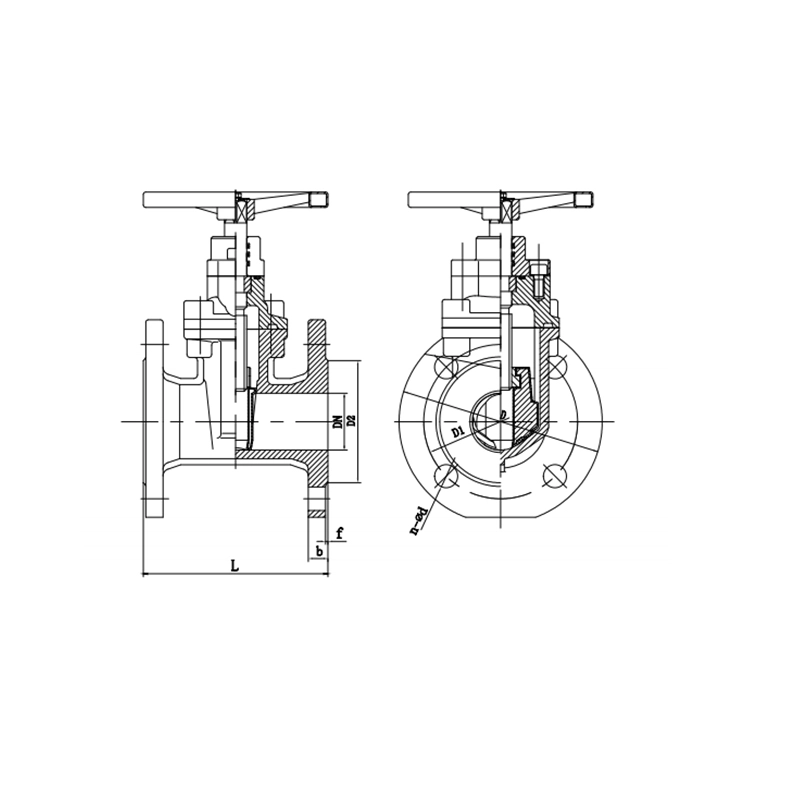
AWWA C509/C515 Non-rising Resilient Gate Valve Z45X Main dimensions(mm)
| DN | L | D | D1 | D2 | b | f | n-ɸd |
| 50 | 178 | 152 | 120.5 | 92 | 19 | 3 | 4-19 |
| 65 | 190 | 178 | 139.5 | 105 | 19 | 3 | 4-19 |
| 80 | 203 | 191 | 152.5 | 127 | 19 | 3 | 4-19 |
| 100 | 229 | 229 | 190.5 | 157 | 24 | 3 | 8-19 |
| 125 | 254 | 254 | 216 | 186 | 24 | 3 | 8-22 |
| 150 | 267 | 279 | 241.5 | 216 | 25.5 | 3 | 8-22 |
| 200 | 292 | 343 | 298.5 | 270 | 28.5 | 3 | 8-22 |
| 250 | 330 | 406 | 362 | 324 | 30 | 4 | 12-26 |
| 300 | 356 | 483 | 432 | 381 | 32 | 4 | 12-26 |
| 350 | 381 | 533 | 476 | 413 | 35 | 4 | 12-29 |
| 400 | 406 | 597 | 539.5 | 470 | 36.5 | 4 | 16-29 |
| 450 | 432 | 635 | 578 | 533 | 39.5 | 4 | 16-32 |
| 500 | 457 | 699 | 635 | 584 | 43 | 4 | 20-32 |
| 600 | 508 | 813 | 749.5 | 692 | 48 | 5 | 20-35 |
Note:1. Other specifications and flange standards are available upon request.
- Design and specifications are subject to change without prior notice.