.png)
.png)


Deluge Valve Model No. YL4X
Deluge Valve Definition and Components
The Deluge Valve Model YL4X is a hydraulically operated, differential diaphragm-type valve that serves as the central control unit for a deluge fire suppression system. It keeps water from entering the system piping until activated, at which point it opens fully to allow water to flood all connected open nozzles simultaneously.
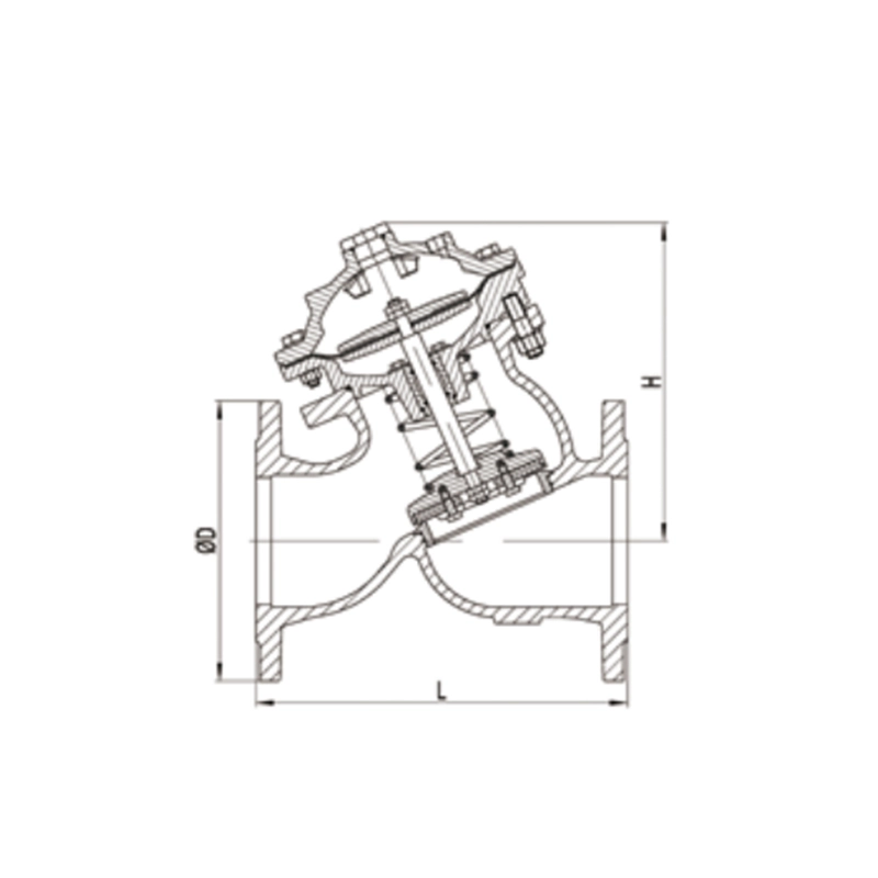
Fire Fighting Deluge Valve Main Parts:
- Valve Body: The main pressure housing.
- Diaphragm Assembly: The flexible disc that seals the valve; pressure differential keeps it closed.
- Diaphragm Cover/Chamber: The upper chamber where control pressure is applied to hold the valve closed.
- Solenoid Valve (Pilot Valve): An electrically operated valve that releases the pressure from the diaphragm chamber to trigger the main valve.
- Manual Release: A mechanical device (lever or button) to open the valve manually.
- Strainer: Protects the solenoid valve and small orifices from debris.
- Pressure Gauges: Indicate supply pressure and diaphragm chamber pressure.
- Trim (Piping & Valves): Includes ball valves for testing and draining.
Role, Characteristics, and Application Scenarios of Deluge Valve in Pipelines
Fire Deluge Valve Function: It acts as a fast-acting, remotely controlled floodgate. Upon receiving a signal from a fire detection system (not from heat-activated sprinklers), it opens completely, delivering water instantly to all open nozzles in the protected hazard area.
Operational Features:
- Dry System Piping: Piping downstream is dry until activation, preventing accidental discharge or freeze damage.
- Remote & Automatic Activation: Triggered by independent fire detectors (heat, smoke, flame, or UV/IR).
- Rapid Opening: Designed for full water flow in seconds.
- Manual Override: Local manual operation is always possible.
- System Reset: Requires manual closing and repriming of the diaphragm chamber.
- Primary Application Scenarios (for high-hazard, fast-spreading fire risks):
- Power Generation: Transformer yards, turbine halls, fuel day tanks.
- Aircraft Industry: Hangars, fuel servicing areas, engine test cells.
- Chemical & Petrochemical: Flammable liquid storage, loading racks, process areas.
- Special Hazards: High-bay warehouses, ammunition storage, museum art storage with gas suppression backup.
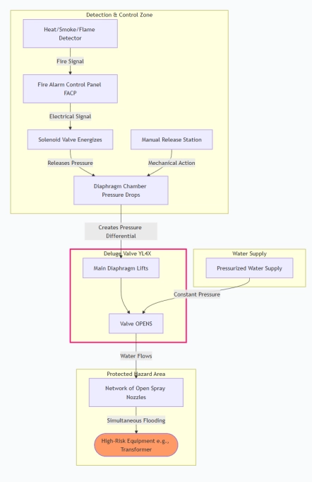
Scenario Diagram:
Deluge Valve Standards: Materials, Design, and Connections
Fire Valve Material Standards:
- Body/Bonnet: Ductile Iron (ASTM A536) or Cast Iron (ASTM A126).
- Trim/Diaphragm Plate: Bronze (ASTM B62) or Stainless Steel (ASTM A276).
- Diaphragm: Reinforced EPDM or Nitrile elastomer.
- Internal Springs: Stainless Steel.
Design & Performance Standards:
- FM Global: Approval Standard for Deluge Valves.
- UL/FM: Listed for fire protection service.
- NFPA 15: Standard for Water Spray Fixed Systems.
- EN 12259-4: Fixed firefighting systems - Components for water mist systems.
Connection Standards:
- Flanged Ends: Most common.
- ANSI/ASME B16.1: Class 125/250 Cast Iron.
- EN 1092-2: PN10/PN16/PN25.
- Threaded Ends: For smaller sizes (e.g., 2").
- Grooved Ends: Per AWWA C606.
How to Select Deluge Valve?
- Define Specifications: Determine required size (e.g., 4", 6"), pressure rating (e.g., 175 psi/12 bar), activation method (electric, pneumatic, hydraulic), and required certifications (UL, FM, LPCB, CFE).
- Source from Approved Manufacturers: Purchase directly from manufacturers (e.g., Tyco/Viking, Reliable, Victaulic) or their authorized distributors with a proven track record in fire protection.
- Request Documentation: Ask for detailed submittal packages, including cut sheets, dimension drawings, FM/UL approval guides, and material specifications.
- Review & Place Order: Ensure the quoted model (YL4X) matches all specs. Confirm lead times, warranty, and spare parts availability. Require factory testing certificates.
Pre-Shipment Inspection for Export Deluge Valve and Key Considerations
Pre-Shipment Inspection Checklist:
Visual & Dimensional:
- Check for physical damage, proper markings (size, pressure rating, model).
- Verify flange dimensions and drilling against order specs.
- Material Verification: Confirm material grades via Mill Test Reports (MTRs) against purchase order.
Functional Testing (Witnessed):
- Hydrostatic Shell Test: Body tested at 1.5x working pressure, no leakage.
- Seat Leakage Test: Valve closed, tested at 1.1x working pressure, acceptable leakage per standard.
- Operational Test: Simulate activation via solenoid and manual release; valve must open and reset smoothly.
- Documentation: Ensure all manuals, test certificates, and approval listings are packed.
Key Export Precautions:
- Complete Drying: After hydrostatic testing, the valve must be completely disassembled, dried internally (using compressed air and desiccant), and reassembled. This is critical to prevent internal corrosion or freezing during transit.
- Protection of Sensitive Parts: The solenoid valve and diaphragm must be individually wrapped in VCI (Vapor Corrosion Inhibitor) paper and protected from impact.
- Flange Protection: Install sturdy plastic or wooden flange protectors bolted in place.
- Packaging: Use export-rated wooden crates with adequate blocking and bracing. Mark clearly with "Fire Protection Equipment," "Fragile," and "Keep Dry."
- Certification Documents: Place a complete set of copies (test reports, MTRs, manuals) in a waterproof pouch inside the crate. The originals should accompany the shipping documents.
Deluge Valve Size Chart