.png)
.png)


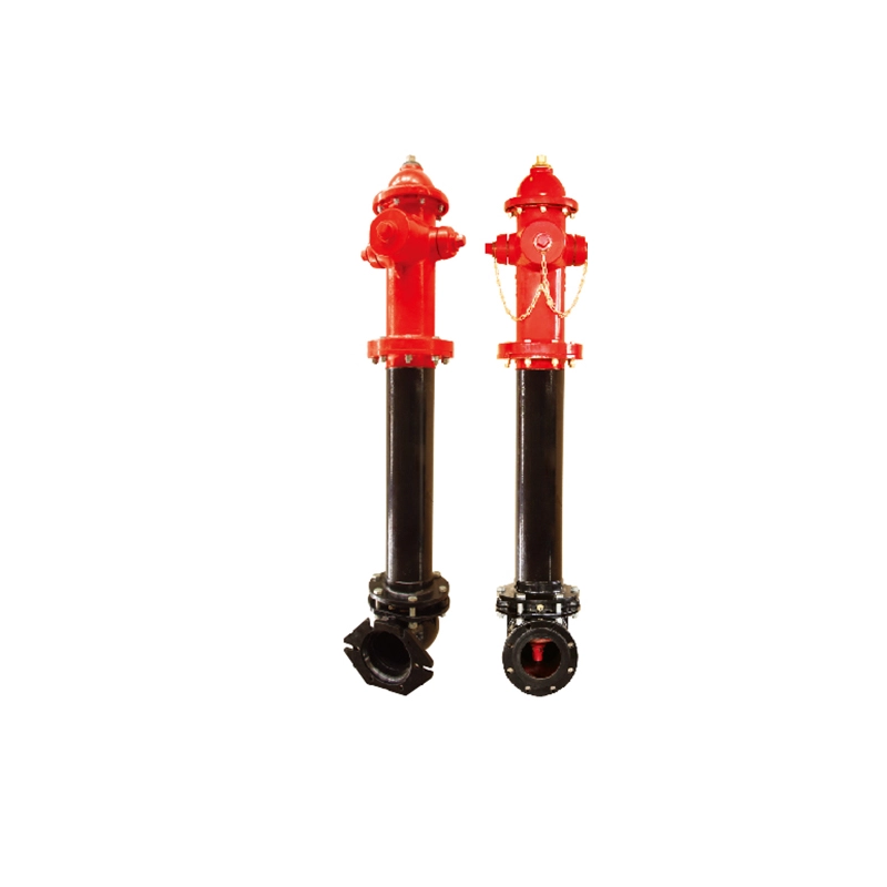
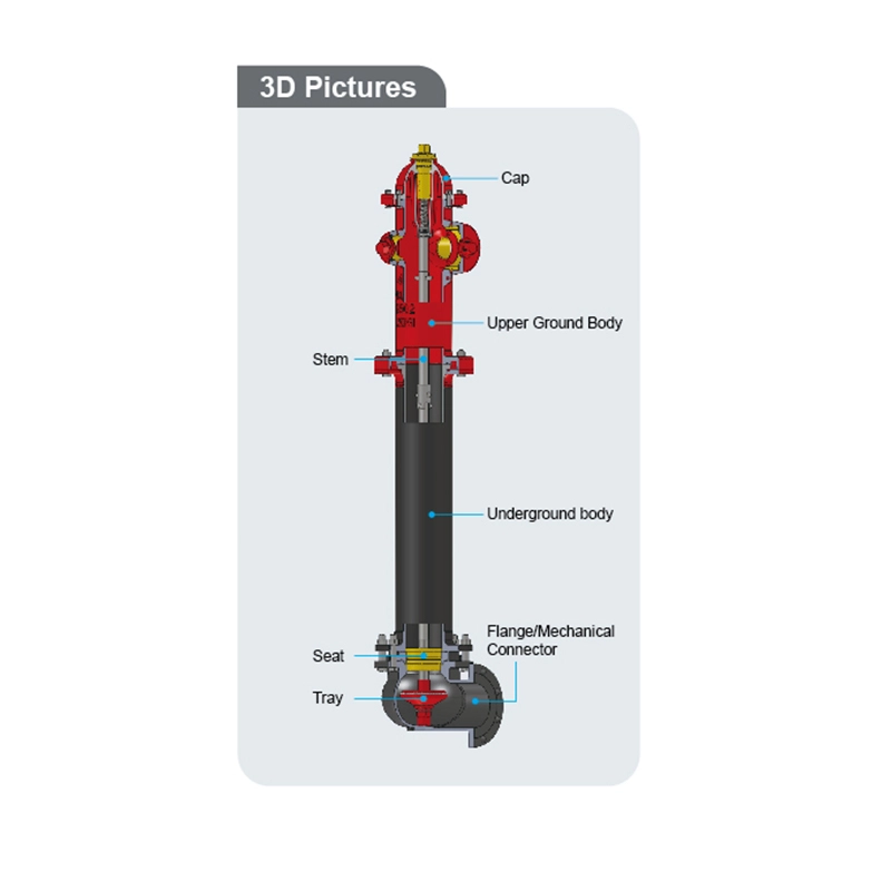
Dry Barrel Fire Hydrant
Dry Barrel Fire Hydrant Technical Features
- Nominal Pressure:250PSl
- Design Standard: AWWA C502
- Inlet flange size:6"(DN150), Main Valve size: 133.4 mm / 5-1/4"
- One pumper nozzle:4.5-4NH thread. Two hose nozzles, 2.5-7.5NH threads
- Other kinds of threads are available
- Mechnical connector:AWWA/ANSI C153 /A21.536 (Model No.: MH-1510A)
- Flange connector:ASME B16.5 CLASS 150 /DIN 2501 PN16 (Model No.: MH-1510FA)
- Painting Details: Red Polyurethane paint & Bitumen Black or painting upon request
- Note: Each hydrant is supplied with a hydrant wrench
- Approvals:UL 246 Listed, FM 1510 Approved
Dry Barrel Fire Hydrant Installation
- Dry Barrel Fire Hydrant should be handled with care to avoid damage. lt is recommended to keep hydrants closed until use
- If the hydrant is not to be used straight away then it is recommended to coat threads and other machined parts with anti-rust oil and the hydrant should be stored in a dry and ventilated area. For long-term storage, the hydrant should be checked regularly
- Before installation of hydrants, the connection should be free from dirt or other matter
- The positioning of the hydrant should be in accordance with local requirements ldeally the pumper should face the street and all connections should be away from any obstruction to connecting hoses
- The inlet elbow should be placed on a solid surface and if possible brace the side opposite the incoming flow to reduce reaction stresses
- The underground parts of the hydrant should be surrounded with coarse gravel for support and drainage
- After the hydrant has been installed and tested, it is recommended to fully flush the hydrant before closing for service. Before replacing the nozzle caps, it is recommended to check for correct drainage of the hydrant on closing of the valve. This can be achieved by placing a hand over the nozzle opening, a suction should be felt
Dry Barrel Fire Hydrant Operation
Unscrew the nozzle caps and connect hoses
- Open the Fire Hydrant using the hydrant key (included) to the fully openposition by turning the operation nut in an anti-clockwise direction. Do not force the hydrant to open further past the fully open position. Note that the hydrant valve is not intended to control the flow, it should be used in either the fully open or fully closed position
- To control flow, a pressure/flow control valve should be fitted to the nozzle outlets on the hydrant
- To close, turn the operation nut into a clockwise direction again, do not Over tighten
Dry Barrel Fire Hydrant Maintenance
- Cary out a visual inspection for signs of significant corrosion which may impair performance
- Where possible, carry out leakage tests by opening one of the nozzle caps slightly and then open the hydrant valve
- Once the air has escaped, tighten the hose cap and check for leaks
- Close Fire Valves and remove one nozzle cap so that the drainage can be checked
- Flush the hydrant
- Clean and lubricate all nozzle threads
- Clean the exterior of the hydrant and repaint if required
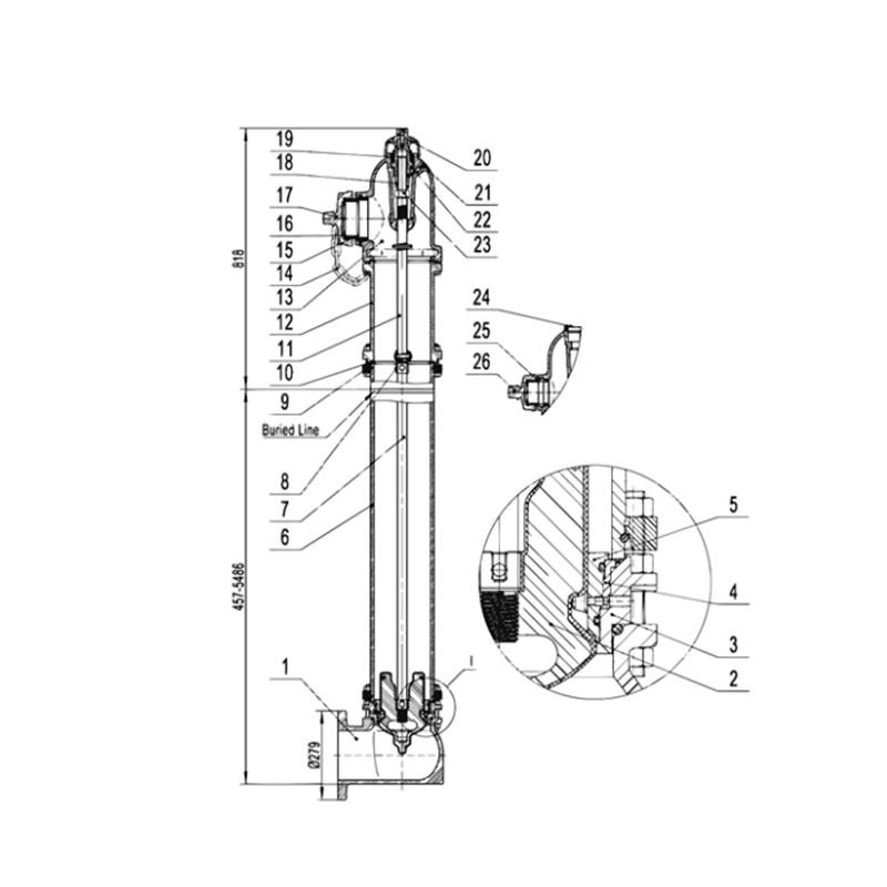
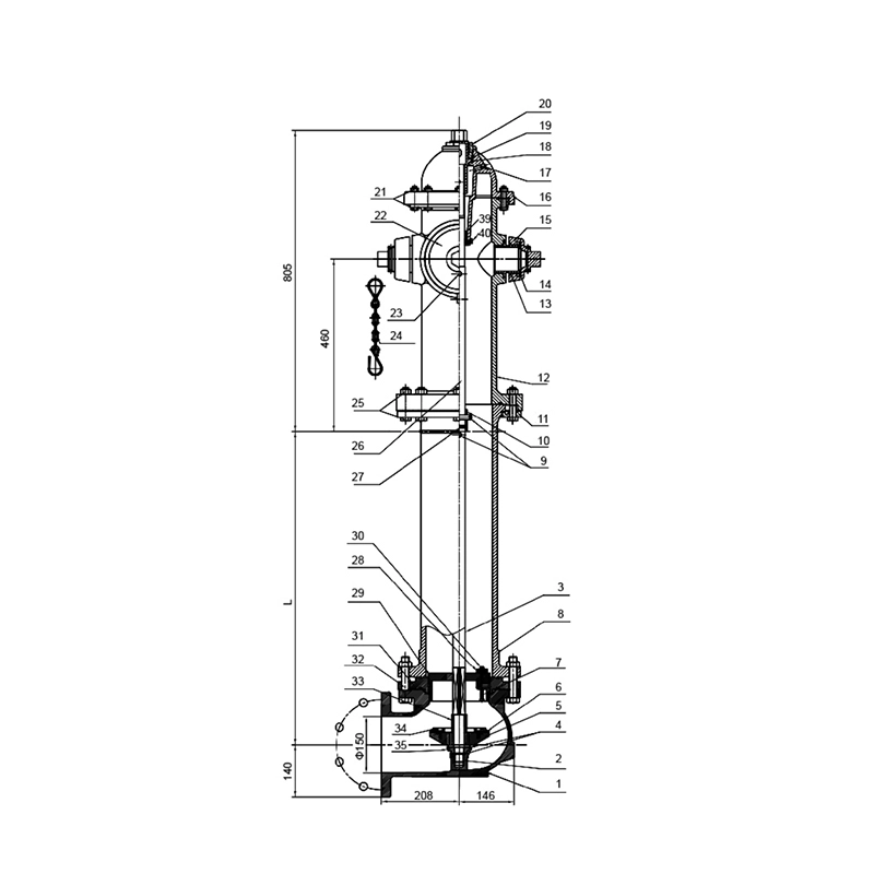
Dry Barrel Fire Hydrant Buried Dimensions
Dry Barrel Fire Hydrant Material List