.png)
.png)


Electric Actuated Flanged Butterfly Valve D941X
Electric Actuated Flanged Butterfly Valve D941X Purpose
This product is used for the water supply and drainage system in tap water, sewage, building, chemical. industries, usually used as an open-close equip rent.
Electric Actuated Flanged Butterfly Valve D941XValve Definition and Components
1.1 What is D941X Electric Actuated Flanged Butterfly Valve?
D941X is a standardized Chinese designation for an electrically operated butterfly valve:
- D: Butterfly Valve
- 9: Electric Actuation
- 4: Flanged Connection
- 1: Center-line/Concentric Design
- X: Resilient (Rubber) Seat
This is a complete automated valve package combining a concentric flanged butterfly valve with an electric motor actuator, designed for remote or automated flow control in piping systems.
1.2 Main Components
| Component | Sub-Components | Material/Type | Primary Function |
| 1. Valve Body Assembly | • Valve Body | Ductile Iron/Cast Steel/Stainless Steel with EPDM/NBR seat | Provides flow control and pressure containment |
| • Disc | |||
| • Stem | |||
| • Resilient Seat | |||
| • Bearings & Seals | |||
| 2. Electric Actuator | • Electric Motor | Industrial-grade motor with IP67/IP68 enclosure | Converts electrical signals to mechanical rotation |
| • Gear Reduction System | |||
| • Limit Switches | |||
| • Torque Switch | |||
| • Control Module | |||
| • Manual Override | |||
| 3. Mounting Assembly | • Bracket/Adapter | Steel or aluminum alloy | Securely connects actuator to valve |
| • Coupling | |||
| • Mounting Bolts | |||
| 4. Control System | • Local Control Box | Electronic components with NEMA 4X/IP65 enclosure | Provides control interface and status indication |
| • Position Feedback | |||
| • Signal Interfaces | |||
| • Power Supply | |||
| 5. Position Indicator | • Mechanical Pointer | Visual/electronic indicators | Shows valve open/closed status |
| • Electronic Position Transmitter |
Key Actuator Types:
- On-Off Type: Simple open/close control
- Modulating Type: Precise positioning (4-20mA/0-10V control)
- Smart/Intelligent: With digital communication (HART, Profibus, Fieldbus)
Role, Characteristics, and Application Scenarios of Electric Actuated Flanged Butterfly Valve D941X in Pipelines
2.1 Pipeline Functions
- Remote Operation: Enables control from control rooms or SCADA systems
- Automated Process Control: Integrates into automated sequences and safety systems
- Emergency Shut-off: Quick response to safety interlocks
- Flow Regulation: Precise control (with modulating actuators)
- Status Monitoring: Feedback of valve position to control systems
2.2 Operational Features
| Feature | Description | Benefit |
| Rapid Operation | Typically 15-60 seconds for 90° rotation | Quick system response |
| High Positioning Accuracy | ±0.5% to ±1% of full scale (modulating type) | Precise flow control |
| Fail-Safe Options | Spring return or battery backup | Safety in power loss |
| Duty Cycle | Continuous or intermittent duty rated | Matches application needs |
| Environmental Protection | IP67/IP68, Explosion-proof options | Suitable for harsh conditions |
| Diagnostic Capabilities | Smart actuators with self-diagnostics | Predictive maintenance |
| Local/Remote Control | Local pushbuttons + remote signals | Operational flexibility |
2.3 Application Scenarios
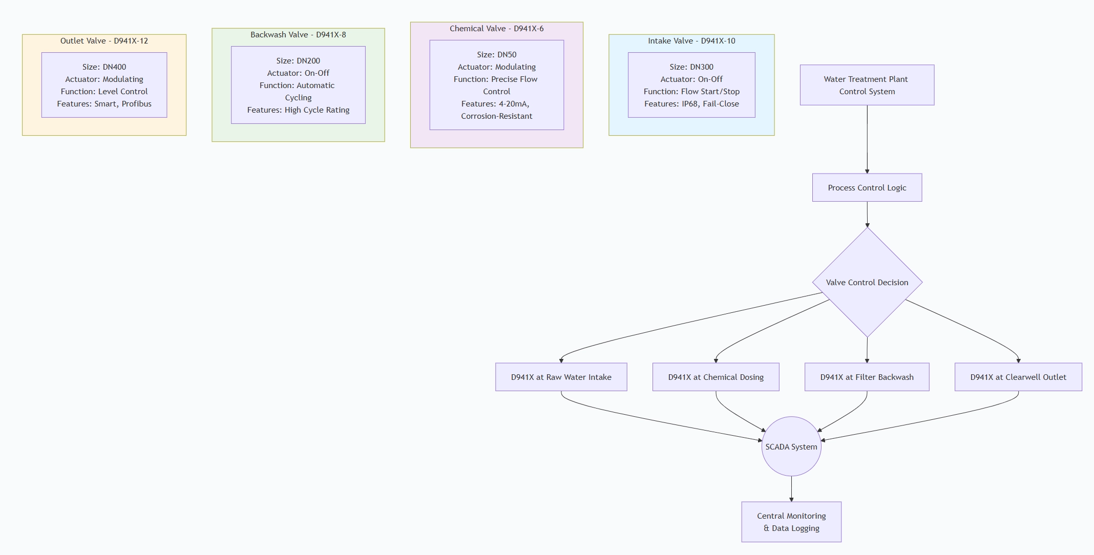
Typical Industry Applications:
- Water/Wastewater Treatment: Pump control, filter sequencing, chemical dosing
- HVAC Systems: Building automation, chilled/heating water control
- Industrial Processes: Batch processing, mixing, filling operations
- Fire Protection: Automatic sprinkler system control
- Irrigation Systems: Automated zone control
- Power Plants: Cooling water, condensate, and feedwater systems
Electric Actuated Flanged Butterfly Valve D941X Standards: Materials, Design, and Connections
3.1 Material Standards
| Component | Standards | Common Materials |
| Valve Body/Disc | ASTM A126, ASTM A216, ASTM A351 | Ductile Iron (QT450-10), WCB, CF8/CF8M |
| Stem | ASTM A276, ASTM A564 | 304SS, 316SS, 17-4PH |
| Seat | FDA, NSF/ANSI 61, WRAS | EPDM, NBR, Viton |
| Actuator Housing | IEC/EN 60529 | Aluminum alloy, reinforced plastic |
| Electrical Components | UL, CSA, CE | Industrial-grade components |
3.2 Fire protection water supply Design Standards
| Standard | Application | Key Requirements |
| API 609 | Butterfly Valve Design | Pressure containment, design life |
| ISO 5211 | Mounting Interface | Actuator-to-valve connection dimensions |
| IEC 60534 | Industrial Process Control Valves | Actuator performance requirements |
| ISO 15848 | Fugitive Emissions | Stem seal leakage requirements |
| ATEX/IECEx | Explosive Atmospheres | Explosion-proof construction |
| SIL | Safety Integrity Level | For safety instrumented systems |
3.3 Connection Standards
| Connection Type | Standards | Common Specifications |
| Flange Connection | ASME B16.5, EN 1092-1, JIS B2220 | Class 150/PN16, RF face |
| Electrical Connection | IEC 60079, NEC | Conduit entry, cable glands |
| Signal Interface | NAMUR, IEC 61131 | 4-20mA, 0-10V, digital protocols |
| Mounting Interface | ISO 5211 | F05-F14 mounting pads |
3.4 Electrical Standards
Protection Class: IP65/IP67/IP68 (IEC 60529)
Explosion Protection: ATEX, IECEx for Zone 1/2, 21/22
Power Supply: 24VDC, 110VAC, 220VAC, 380VAC, 50/60Hz
Insulation Class: Class F or H (155°C or 180°C)
Duty Rating: S2 (short-time duty) or S4 (intermittent duty)
How to Select Electric Actuated Flanged Butterfly Valve D941X
4.1Butterfly Valve for Water Specification Development Process
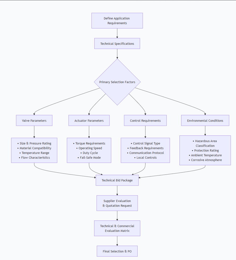
4.2 Critical Specification Elements
- Valve Specifications:
- Size: DN50 to DN1200 (2" to 48")
- Pressure Class: PN10/PN16/Class 150
- Body Material: Based on fluid compatibility
- Seat Material: EPDM (water), NBR (oil), Viton (chemicals)
- End Connection: Flange type and standard
Actuator Specifications:
- Torque Requirement: Calculate based on valve size, pressure, and frequency
- Required Torque = Valve Breakaway Torque × Safety Factor (1.5-2.0)
- Operation Time: 15, 30, 60 seconds/90°
- Power Supply: Voltage and phase
- Duty Cycle: Continuous (S4) or intermittent (S2)
- Fail-Safe Mode: Spring return (FC/FO) or battery backup
- Protection: IP rating, explosion-proof certification
Control Requirements:
- Control Signal: Discrete (24VDC) or analog (4-20mA)
- Position Feedback: Potentiometer, encoder, or switches
- Communication: HART, Profibus, Foundation Fieldbus
- Local Controls: Handwheel, pushbuttons, selector switch
- Diagnostics: Smart features, predictive maintenance
Environmental Requirements:
- Ambient Temperature: -20°C to +70°C standard
- Hazardous Area: ATEX Zone 1, 2, 21, 22
- Special Conditions: Submersion, washdown, corrosive atmosphere
4.3Fire Protection System Supplier Evaluation Criteria
| Evaluation Area | Weight | Key Criteria |
| Technical Compliance | 30% | • Meets all specifications |
| • Valid certifications | ||
| • Engineering support | ||
| Quality & Reliability | 25% | • ISO 9001 certification |
| • Testing procedures | ||
| • MTBF data | ||
| Delivery & Service | 20% | • Lead time |
| • Technical support | ||
| • Spare parts availability | ||
| Cost Effectiveness | 15% | • Initial cost |
| • Lifecycle cost | ||
| • Energy efficiency | ||
| Experience & References | 10% | • Similar applications |
| • Customer testimonials |
4.4 Order Documentation
Ensure purchase order includes:
Detailed technical data sheets
Approved vendor list for critical components
Inspection and test plan (ITP)
Documentation deliverables list
Warranty terms and conditions
Spare parts requirements
Pre-Shipment Inspection for Export Electric Actuated Flanged Butterfly Valve D941X and Key Considerations
5.1 Comprehensive Inspection Protocol
Stage 1: Documentation Review
- Material certificates (EN 10204 3.1 for metallic parts)
- Actuator certification (ATEX, CSA, UL if applicable)
- Electrical component certificates (CE, RoHS)
- Test reports for valve and actuator
- Calibration certificates for test equipment
- Operation and maintenance manuals
Stage 2: Visual Inspection
| Item | Check Points | Acceptance Criteria |
| Valve Assembly | Surface finish, markings, coating | No defects, proper identification |
| Actuator | Housing integrity, nameplate | Proper ratings, no damage |
| Electrical Connections | Cable entries, terminal blocks | Proper sealing, secure connections |
| Mechanical Assembly | Mounting bolts, coupling alignment | Proper torque, no misalignment |
| Paint/Coating | Uniformity, thickness | Per specification, no runs or sags |
Stage 3: Dimensional Verification
- Face-to-face dimensions per ISO 5752
- Flange dimensions per specified standard
- Actuator mounting per ISO 5211
- Overall dimensions for shipping
Stage 4: Functional Testing
Mechanical Operation Test:
Test Procedure:
- Manual Operation: Verify handwheel operation
- Electric Operation: Full open/close cycles (3-5 times)
- Torque Verification: Confirm within actuator rating
- Speed Test: Verify opening/closing time
- Limit Switches: Test open/close position stops
- Electrical Testing:
Insulation resistance: >100MΩ at 500VDC
Dielectric strength: 1500VAC for 1 minute
Motor current: Within nameplate rating
Control functions: Test all modes (local/remote/auto)
- Pressure Testing (Valve):
- Shell test: 1.5 × PN for ≥2 minutes
- Seat test: 1.1 × PN both directions
- Test medium: Water or air per API 598
Integrated Performance Test:
- End-to-end control signal test (4-20mA positioning)
- Fail-safe operation (if applicable)
- Communication protocol verification (if smart)
- Environmental simulation (if specified)
5.2 Special Considerations for Electric Actuators
Environmental Sealing Verification:
- IP67/IP68 submersion test (if specified)
- Conduit entry sealing check
- Housing gasket integrity
Explosion-Proof Requirements:
- Verify certification matches hazardous area classification
- Check flame path gaps
- Ensure proper cable gland certifications
Smart Features Verification:
- Communication protocol testing
- Diagnostic functions
- Configuration software operation
5.3 Export Preparation Checklist
Preservation:
- Internal drying after hydrotest
- Application of VCI (Vapor Corrosion Inhibitor) to metal surfaces
- Desiccant placement in actuator housing (if vented)
- Protective coating on machined surfaces
Protective Packaging:
- Individual Valve Protection:
- Flange face protection with 3mm plastic/metal covers
- Actuator shrouding with moisture barrier
- Valve disc secured in slightly open position
Crating Requirements:
- ISPM-15 compliant wood for international shipment
- Internal blocking and bracing
- Vibration dampening for sensitive components
- Separate packaging for accessories/ documentation
Marking and Labeling:
CRATE MARKING:
- Consignee/consignor details
- Handling instructions (fragile, keep dry, this side up)
- Package number and gross/net weight
- Hazard labels (if lithium batteries in actuators)
VALVE/ACTUATOR LABELING:
- Nameplate with all ratings
- Electrical classification labels
- Directional arrows
- Serial numbers for traceability
Documentation Package:
REQUIRED DOCUMENTS PER CONTAINER:
Commercial Documents:
- Commercial Invoice (3 copies)
- Packing List (detailed by crate)
- Certificate of Origin
- Bill of Lading
Technical Documents:
- Final Test Reports
- Material Certificates
- Certifications (ATEX, CE, etc.)
- Calibration Certificates
- Installation, Operation, Maintenance Manuals
- Spare Parts List
Shipping Documents:
- Insurance Certificate
- Export Declaration
- Dangerous Goods Declaration (if applicable)
Special Precautions for Electric Actuators:
Battery-Powered Units:
- Verify state of charge
- Include battery safety data sheets
- Comply with IATA/IMDG regulations if shipping separately
Electronic Components:
- ESD protection during handling
- Humidity indicators in packaging
- Temperature monitoring for extreme climates
Communication Modules:
- Configuration backup
- Default settings documentation
- Software version documentation
5.4 Third-Party Inspection Requirements
For critical applications, consider:
- Factory Acceptance Test (FAT) witness
- Third-party inspection (SGS, BV, DNV)
- Witnessed performance testing
- Random sampling for batch orders
FAT Checklist Example:
FACTORY ACCEPTANCE TEST PROTOCOL
- Document Review: Complete and approved
- Visual Inspection: Pass
- Dimensional Check: Within tolerance
- Pressure Tests: Shell/Seat passed
- Electrical Tests: All parameters OK
- Functional Tests: Full operation verified
- Control Tests: Signal response confirmed
- Safety Tests: All interlocks functional
- Packaging Inspection: Export ready
5.5 Final Release Criteria
Before shipping authorization:
All tests completed and documented
Non-conformities resolved and closed
Documentation package complete
Packaging meets export requirements
Shipping marks properly applied
Customs documentation prepared
Insurance arranged
Carrier instructions provided
5.6 Common Issues to Prevent
| Issue | Prevention Measure |
| Moisture Damage | Desiccants, moisture barrier bags |
| Vibration Damage | Proper blocking and bracing |
| Electrical Damage | Surge protection during testing |
| Corrosion | Complete drying, VCI application |
| Documentation Errors | Cross-check against packing list |
By implementing this comprehensive inspection and preparation protocol, you ensure D941X electric actuated butterfly valves arrive at their destination fully functional and ready for installation, minimizing startup issues and ensuring long-term reliable operation.
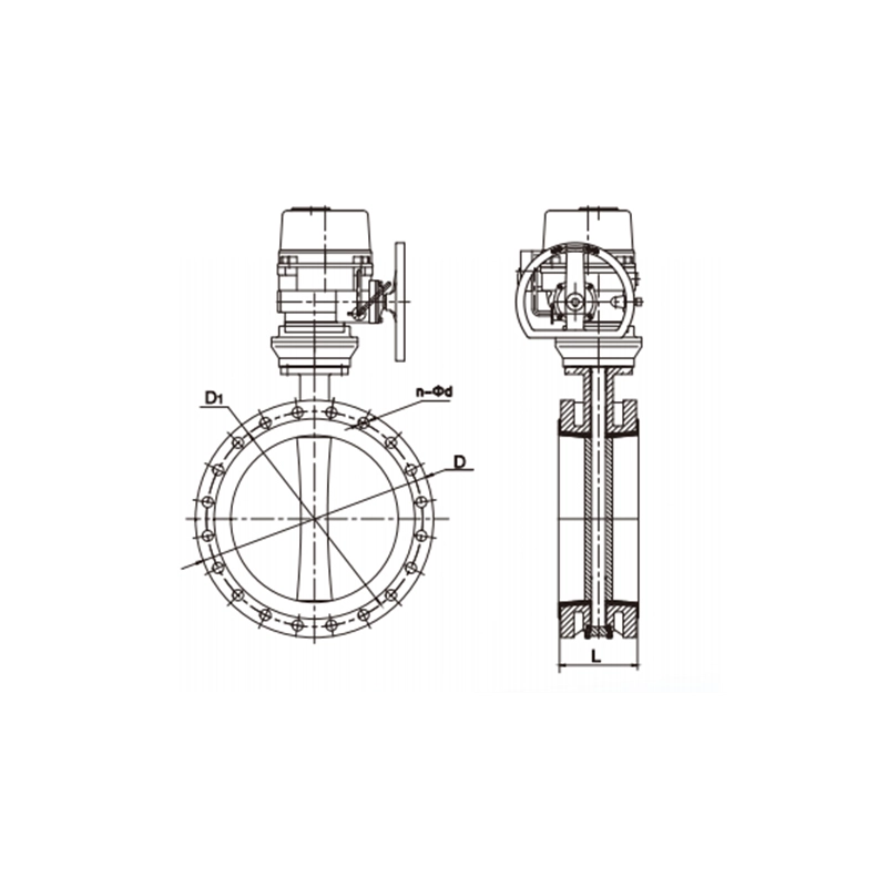
Electric Actuated Flanged Butterfly Valve D941X Main dimensions(mm)
Note:1. Other specifications and flange standards are available upon request.
- Design and specifications are subject to change without prior notice.