.png)
.png)


Mechanical Gate Valve MJZ45X
Mechanical Gate Valve MJZ45X Purpose
Este fire protection water supply is mounted on various pipelines and used as a bi—way closed circuit equipment for tap water, sewage treatment, metallurgy, petroleum, building, chemical, electric power industries etc.
Mechanical Gate Valve Definition and Components
1.1 What is an MJZ45X Mechanical Joint Non-rising Resilient Gate Valve?
MJZ45X is a specialized waterworks gate valve featuring Mechanical Joint (MJ) connections, designed specifically for ductile iron water piping systems:
- MJ: Mechanical Joint connection (AWWA C111 standard)
- Z: Válvula de compuerta
- 45: Non-rising stem, flanged design
- X: Resilient (rubber) seat
This is a restrained joint Válvula de compuerta para agua specifically engineered for water distribution systems where thrust restraint is required without external anchoring. The Mechanical Joint provides both sealing and restraint against pipe separation due to internal pressure or external loads.
1.2 Main Components (MJ-Specific Design)
| Componente | MJ-Specific Features | Normas materiales |
| 1. Valve Body with MJ Ends | Integral MJ bell ends with groove for gland and gasket; designed for AWWA C111 compatibility | Ductile Iron ASTM A536 65-45-12 |
| 2. Puerta resistente | Full rubber encapsulation with thicker edge protection for MJ restraint forces | Cast iron core + EPDM/NBR rubber (NSF/ANSI 61) |
| 3. Vástago no ascendente | Heavy-duty stainless steel with increased diameter for MJ restraint loads | Type 316 SS, ASTM A276 |
| 4. MJ Gland | Special bolted gland that compresses gasket and provides restraint | Ductile Iron, hot-dip galvanized per ASTM A153 |
| 5. MJ Gasket | Wedge-shaped rubber gasket for pressure-activated sealing | EPDM rubber per AWWA C111 |
| 6. T-head Bolts & Nuts | For gland assembly; provide uniform compression | Carbon steel, ASTM A307 Grade B, galvanized |
| 7. Thrust Washers | Between gland and pipe; distribute load evenly | Ductile iron or steel |
| 8. Protective Coatings | Fusion-bonded epoxy (FBE) internally and externally | Per AWWA C550 |
Role, Characteristics, and Application Scenarios of Mechanical Gate Valve in Pipelines
2.1 Funciones del gasoducto
- Restrained Joint Isolation: Provides both shutoff and thrust restraint in one assembly
- Main Line Control: Primary isolation valve in pressurized water transmission mains
- Pressure Zone Boundary: Separation between different pressure zones with restraint capability
- System Integrity: Maintains pipeline continuity during pressure surges and water hammer
- Zero-Leakage Sealing: Bubble-tight closure with resilient seating
2.2 MJ-Specific Operational Features
| Característica | Mechanical Joint Advantage | Beneficio operativo |
| Restrained Connection | Gland bolts provide positive restraint against separation | Eliminates need for thrust blocks or anchor harnesses |
| Pressure-Activated Seal | Higher pressure creates tighter seal | Self-sealing under pressure, reliable performance |
| Field Flexibility | Can be installed with standard MJ accessories | Compatible with existing ductile iron systems |
| Angular Deflection | Allows up to 5° deflection at each joint | Accommodates minor alignment variations |
| Retention Groove | Positive locking of gasket in valve bell | Prevents blow-out during pressure surges |
| Standardization | Conforms to AWWA C111 dimensions | Interchangeable with other MJ components |
2.3 Diagrama del escenario de aplicación
| Application Scenario | Valve Size Range | Special MJ Features | Reason for Selection |
| Water Transmission Mains | 16"-48" | Heavy-duty glands, extra bolts | Restraint for long straight runs |
| Vertical Installations | 8"-24" | U-bolt restraint option | Prevents valve settlement |
| Subaqueous Crossings | 12"-36" | Corrosion-resistant coating | Restraint without external anchors |
| High Pressure Zones | 6"-30" | High-pressure gaskets | Sealing improves with pressure |
| Earthquake Zones | 8"-24" | Flexible joint design | Accommodates ground movement |
Mechanical Gate Valve Normas: Materiales, diseño y conexiones
3.1 Fire Protection Valves and Fittings Normas materiales
| Componente | MJ-Specific Standards | Material Requirements |
| Valve Body with MJ Bell | AWWA C111, AWWA C509 | Fundición dúctil según ASTM A536 65-45-12 |
| MJ Gland | AWWA C111 | Ductile Iron, minimum thickness per pressure class |
| MJ Gasket | AWWA C111, NSF/ANSI 61 | EPDM rubber, wedge profile, pressure-rated |
| T-head Bolts | AWWA C111 | Carbon steel, ASTM A307 Grade B, hot-dip galvanized |
| Vástago | AWWA C509 | 316 Stainless Steel, increased diameter for MJ restraint |
| Protective Coatings | AWWA C550 | Fusion-bonded epoxy, 10-16 mils minimum |
3.2 Normas de diseño
| Estándar | Título | MJZ45X Application |
| AWWA C111 | Rubber-Gasket Joints for Ductile-Iron Pressure Pipe and Fittings | Defines MJ end dimensions and joint assembly |
| AWWA C509 | Válvulas de compuerta con asiento elástico para suministro de agua | Valve design and performance requirements |
| AWWA C550 | Protective Interior and Exterior Coatings for Valves | Requisitos de revestimiento para la protección contra la corrosión |
| AWWA C600 | Installation of Ductile-Iron Mains and Their Appurtenances | Installation guidelines for MJ valves |
| ANSI/AWWA C151 | Ductile-Iron Pipe, Centrifugally Cast | Pipe compatibility for MJ connections |
3.3 Normas de conexión
Mechanical Joint (MJ) Specifications:
- Joint Type: AWWA C111 Standard Mechanical Joint
- Pressure Rating: 150 psi (standard), 200 psi (high pressure), 350 psi (test pressure)
- Deflection Allowance: Up to 5° per joint
- Restraint Method: Gland bolts provide positive restraint
- Gasket Type: Wedge-shaped EPDM, pressure-activated
MJ End Dimensions (Example - 12" Valve):
- Bell Inside Diameter: 13.50"
- Bell Depth: 4.00"
- Gland Width: 1.50"
- Bolt Circle: 17.00"
- Number of Bolts: 8
- Bolt Size: 1" diameter
How to Select Mechanical Gate Valve
4.1 Proceso de elaboración de especificaciones
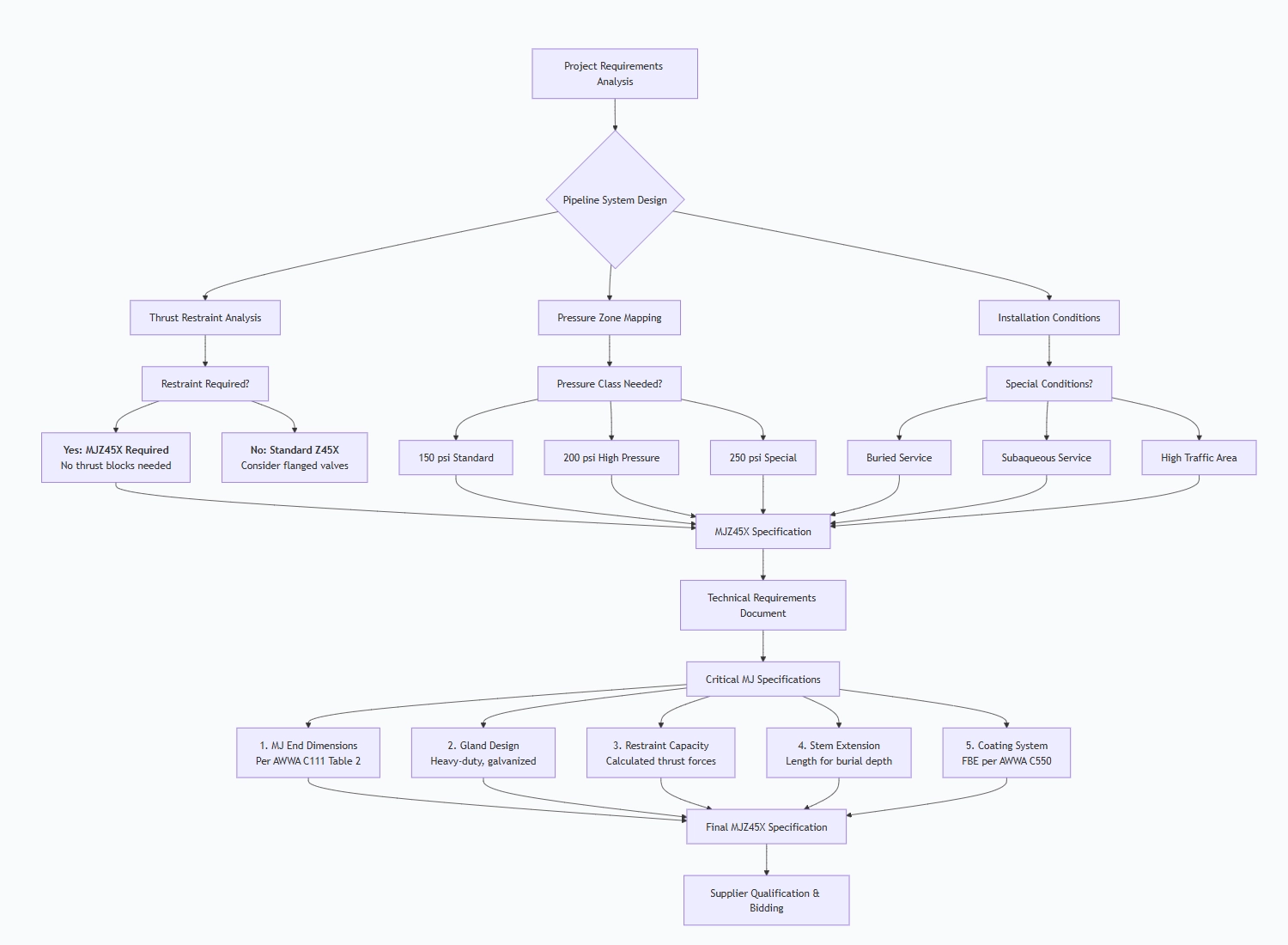
4.2 Critical MJ-Specific Specifications
Mechanical Joint Requirements:
MJ END SPECIFICATIONS:
- Standard: AWWA C111 Mechanical Joint
- Pressure Class: 150 or 200 psi
- Gland Type: Heavy-duty, ductile iron
- Gasket Material: EPDM per AWWA C111
- Bolting: T-head bolts, hot-dip galvanized
- Bolt Torque: Specify installation torque values
Restraint Capacity Calculations:
- Design Thrust Force: Calculate based on maximum operating pressure
- Safety Factor: Minimum 2:1 safety factor for restraint
- Soil Conditions: Consider burial depth and soil type for additional restraint needs
- Test Pressure: Ensure MJ assembly can withstand 350 psi test pressure
Stem Extension Requirements:
- Burial Depth: Determine operating nut depth below grade
- Extension Type: Two-piece or single-piece design
- Material: Galvanized steel or coated ductile iron
- Operation: Square drive size (2" minimum for valves ≥12")
Special Conditions:
- Subaqueous Service: Enhanced corrosion protection, cathodic protection provisions
- Traffic Loads: Heavy-duty construction for high traffic areas
- Seismic Zones: Flexible joint allowances, additional restraint considerations
4.3 Requisitos de cualificación de los proveedores
Mandatory MJ-Specific Qualifications:
- AWWA C111 Manufacturing License: For MJ end production
- AWWA C509 License: For valve manufacturing
- MJ Tooling Verification: Proper molds and tooling for MJ bells
- Gland Production Capability: In-house gland manufacturing or certified supplier
- Assembly Testing: Facilities for MJ joint assembly testing
Factory Audit Checklist for MJ Valves:
- MJ Bell Casting: Verify dimensional control and quality
- Gland Manufacturing: Check machining and coating processes
- Assembly Procedures: Review MJ assembly torque procedures
- Testing Capabilities: Pressure testing of assembled MJ joints
- Quality Control: Dimensional verification of MJ components
4.4 Purchase Documentation Requirements
MJ-Specific Items to Include in PO:
- AWWA Standard References: C111, C509, C550
- MJ Dimension Table: Reference to specific AWWA C111 table
- Gland and Gasket Requirements: Material and dimensional specifications
- Assembly Instructions: Torque values and assembly sequence
- Field Installation Kit: If including installation tools
- Spare Parts List: Gaskets, bolts, glands for field use
Pre-Shipment Inspection for Export Mechanical Gate Valve and Key Considerations
5.1 MJ-Specific Inspection Protocol
Phase 1: Documentation Review (MJ-Specific)
MJZ45X REQUIRED DOCUMENTS:
- AWWA C111 Compliance Certificate for MJ ends
- MJ Gland and Gasket Material Certificates
- Bolt and Nut Certifications (ASTM A307, galvanizing cert)
- Dimensional Reports for MJ bells (per AWWA C111 Table 2)
- Assembly Torque Procedure Documentation
- Restraint Capacity Calculations
- Certificados de revestimiento (FBE según AWWA C550)
Phase 2: MJ End Dimensional Inspection
| Inspección | AWWA C111 Requirement | Measurement Method |
| Bell ID | Per Table 2 for size and class | Inside micrometers |
| Bell Depth | Minimum per standard | Depth gauge |
| Gland Dimensions | Width, thickness, bolt holes | Calipers, templates |
| Bolt Circle | Diameter tolerance 卤1/16" | Bolt circle gauge |
| Gasket Groove | Width and depth | Profile gauge |
| Acabado superficial | Smooth, free of defects | Comparador visual, de superficie |
Phase 3: Material and Coating Verification
- PMI Testing: Verify ductile iron grade and stainless steel stem
- Coating Thickness: FBE coating 10-16 mils (AWWA C550)
- Adhesion Test: Cross-hatch test per ASTM D3359
- Holiday Detection: 67.5 volts per mil of coating (for FBE)
Phase 4: MJ Assembly and Testing
MJ Joint Assembly Test:
Procedimiento de prueba:
- Assemble MJ gland and gasket on test pipe spool
- Torque bolts to specified values (typically 75-150 ft-lbs)
- Perform hydrostatic test at 350 psi for 2 minutes
- Check for leakage at MJ joint
- Disassemble and inspect gasket compression
Valve Pressure Testing (Per AWWA C509):
- Shell Test: 300 psi for 2 minutes (for 150 psi valve)
- Seat Test: 150 psi bubble-tight, both directions
- MJ End Test: Test with assembled MJ connections if possible
Restraint Verification:
- Pull Test: Apply calculated thrust force to verify restraint
- Torque Verification: Check gland bolt torque values
- Gasket Compression: Measure compressed gasket thickness
5.2 Special MJ Considerations
Gland and Gasket Inspection:
- Verify gasket is correct wedge profile for MJ
- Check gland casting for defects affecting restraint
- Ensure T-head bolts have proper galvanizing
- Verify gland fits valve bell properly
Assembly Procedure Verification:
- Check that assembly instructions are clear and complete
- Verify torque values are appropriate for bolt size
- Ensure proper bolt tightening sequence is documented
- Check that lubrication requirements are specified
5.3 Protocolo de preparación de las exportaciones
MJ End Protection:
CRITICAL PROTECTION REQUIREMENTS:
- MJ Bell Protection: Heavy-duty plastic caps with retention straps
- Gland Protection: Separate packaging with corrosion protection
- Gasket Protection: Sealed plastic bags with desiccant
- Bolt Protection: Coated or bagged with VCI protection
- Thread Protection: Plastic caps on all threaded components
Packaging Configuration:
- Valve Body: Crated separately with MJ bells protected
- Gland Assembly: Packed in separate box within main crate
- Gaskets and Bolts: Sealed packages with part numbers
- Stem Extension: If provided, packed separately with supports
- Installation Tools: Special kit if included in order
MJ-Specific Marking:
Crate Marking:
MJ VALVE - MECHANICAL JOINT
- TAMAÑO: [Diámetro]
- AWWA C111 / C509
- PRESSURE: 150/200 psi
- CONTAINS: Valve, Gland, Gaskets, Bolts
- HANDLE WITH CARE - DO NOT DROP
Component Marking:
- Valve body: Size, pressure rating, AWWA standards
- Gland: Size, part number, material
- Gaskets: Size, material, pressure rating
- Bolts: Size, grade, quantity
- Documentation Package (MJ-Specific):
Documentos técnicos:
- MJ Assembly Drawings: Detailed assembly instructions
- Torque Specifications: Bolt torque values and sequences
- Installation Manual: Field installation procedures
- Restraint Calculations: Engineering calculations for thrust forces
- Test Reports: MJ joint assembly test results
Documentos de certificación:
- AWWA C111 Compliance Certificate
- MJ Gland and Gasket Material Certificates
- Bolt and Nut Material Certifications
- Certificados de revestimiento (FBE según AWWA C550)
- Certificación NSF/ANSI 61 para todas las piezas húmedas
5.4 Special Precautions for MJ Valves
Joint Protection During Shipping:
- Bell Protection: Rigid caps that withstand stacking loads
- Gland Protection: Prevent distortion of gland during transit
- Thread Protection: All threads must be protected from damage
- Coating Protection: Prevent abrasion of FBE coating
Climate Considerations:
- Gasket Storage: EPDM gaskets must be protected from ozone and UV
- Temperature Limits: Store between -10°C and +40°C
- Humidity Control: Desiccant in all packages containing metal parts
Handling Instructions:
- Lifting Points: Use designated lifting lugs only
- Stacking Limitations: Maximum stacking height based on crate design
- Orientation: Keep valve in horizontal position during transport
- Securing: Adequate blocking and bracing in shipping container
5.5 Lista de comprobación de la inspección final
Antes del cierre de la caja:
- MJ bell protection caps installed and secured
- Gland assembly properly packaged and labeled
- Gaskets and bolts in sealed, labeled packages
- All components accounted for per packing list
- Internal bracing to prevent movement
- Desiccant and moisture indicators placed
- Documentation package in waterproof pouch
MJ-Specific Checks:
- MJ dimensions verified against AWWA C111
- Gland fit-up checked on valve bell
- Bolt holes aligned and clean
- Gasket groove free of defects
- Coating intact on all MJ surfaces
- Threads protected on all bolting
5.6 Common MJ-Specific Issues to Prevent
| Problema potencial | Método de prevención | Método de inspección |
| Bell Damage | Rigid protection caps | Visual inspection, dimensional check |
| Gland Distortion | Proper packaging supports | Flatness check, fit-up test |
| Coating Damage | Edge protection, careful handling | Holiday detection, visual inspection |
| Thread Damage | Thread protectors, proper storage | Thread gauge check |
| Gasket Degradation | UV protection, proper storage | Durometer check, visual inspection |
| Component Mix-up | Clear labeling, separate packaging | Part number verification |
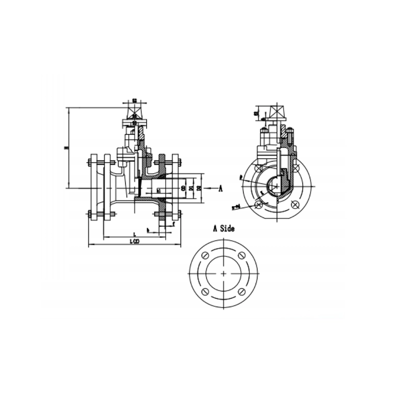
Mechanical Gate Valve Main dimensions(mm)
| DN | OD | D‹ | Dz | K | D | h1 | n-ed | L | L(z) | b | f |
| 50 | 63 | 69 | 88 | 125 | 165 | 58 | 4—19 | 178 | 250 | 19 | 3 |
| 65 | 75 | 80 | 105 | 145 | 185 | 63.5 | 4—1e | 1so | 260 | 19 | 3 |
| 80 | 90 | 96 | 116 | 160 | 200 | 63.5 | 4-19 | 203 | 280 | 19 | 3 |
| 100 | 110 | 116 | 121.2 | 185 | 220 | 63.5 | 4-19 | 229 | 315 | 19 | 3 |
| 150 | 160 | 166 | 194 | 240 | 285 | 63.5 | 8—23 | 267 | 350 | 19 | 3 |
| 200 | 225 | 231 | 258 | 295 | 340 | 63.5 | 12—23 | 292 | 390 | 20 | 3 |
| 250 | 280 | 286 | 315 | 370 | 420 | 63.5 | 12-28 | 330 | 425 | 22 | 4 |
Nota:1. Otras especificaciones y normas de brida disponibles bajo pedido.
2. Design and specifications are subject to change without prior notice.