.png)
.png)


Flanged Metal-seat Butterfly Valve D343HD343F
Flanged Metal-seat Butterfly Valve D343HD343F Purpose
Butterfly valve for the petroleum, chemical, food, medicine,metallurgy, shipbuilding, paper, industrial environmental protec tion water supply and drainage, on high-level pipeline architecture can be in a variety of corrosive,non-corrosive gases,liquids, fluids and solid powder loaded pipelines and containers for the head stock or adjust the medium flow purposes.
Flanged Metal-seat Butterfly Valve D343HD343F Performance parameters
| DN(mm) Nominal diameter | 50~2000 | |||
| PN(MPa) Nominal pressure | 1.0 | 2.5 | 150LB | |
| Testing
pressure |
Shell | 1.5 | 3.75 | 4.0 |
| Sealing | 1.1 | 2.75 | 3.0 | |
| Working temperature(℃) | -40~570 | |||
| Suitable mediums | Water, sea water, air, oils,acids alkali etc | |||
Flanged Metal-seat Butterfly Valve D343HD343F Definition and Components
1.1 What are D343H/D343F Valves?
D343H/D343F are triple eccentric flanged metal-seated butterfly valves designed for extreme service conditions where resilient-seated valves would fail.
Code Breakdown:
- D: Butterfly Valve
- 3: Driving Mode (Manual Gear Operation)
- 4: Flanged Connection
- 3: Triple Offset/Triple Eccentric Design
- H/F: Seat Material Designation
- H: Stainless Steel or Hard-faced Metal Seat
- F: Special Alloy Seat (e.g., Stellite, Inconel, Monel)
1.2 The Triple Eccentric Design Principle
- Eccentricity 1: Stem offset from disc centerline
- Eccentricity 2: Stem offset from valve centerline
- Eccentricity 3: Seat cone angle offset (typically 5-10°)
RESULT: Disc lifts completely away from seat during rotation, achieving ZERO CONTACT until final closure.
1.3 Main Components
| Component | Material/Description | Critical Function |
| 1. Valve Body | ASTM A216 WCB/WCC, A351 CF8/CF8M, A995 Duplex | Pressure-containing structure with precision-machined seat pocket |
| 2. Disc | Base material matching body + Hard-facing (Stellite 6, WC, CrC) | Triple-offset design with conical sealing surface |
| 3. Metal Seat Ring | • D343H: 304SS, 316SS, 17-4PH | Replaceable precision-machined ring providing primary sealing surface |
| • D343F: Stellite 6/21, Inconel 625, Monel K500 | ||
| 4. Stem | Forged 17-4PH, 316SS, or high-strength alloys | Triple-offset positioning, transmits torque without bending |
| 5. Bearing System | Self-lubricating bronze/PTFE, needle roller bearings | Supports eccentric loads, ensures smooth operation |
| 6. Sealing System | • Stem seals: Spring-energized PTFE/Graphite | Secondary sealing, fugitive emission control |
| • Body seals: Spiral-wound gaskets | ||
| 7. Actuator Mount | ISO 5211 standard mounting pad | Interface for gear operators or powered actuators |
Role, Characteristics, and Application Scenarios of Flanged Metal-seat Butterfly Valve D343HD343F in Pipelines
2.1 Pipeline Functions
Absolute Isolation: Zero-leakage shutoff in both directions
High-Temperature Containment: Reliable operation where elastomers fail
Fire-Safe Performance: Inherent metal-to-metal sealing
Abrasive/Corrosive Service: Resists particle erosion and chemical attack
Cryogenic to Ultra-High Temperature: Wide operational range (-196°C to +815°C)
2.2 Operational Features
| Feature | Technical Advantage | Operational Benefit |
| Zero Friction Design | No seat contact during 89° of rotation | Minimal torque, extended cycle life (>100,000 cycles) |
| Bidirectional Sealing | Symmetrical disc/seat geometry | Equal performance in either flow direction |
| Thermal Compensation | Differential expansion accommodation | Maintains seal across wide temperature swings |
| Fire-Safe by Design | All-metal construction | No soft parts to degrade in fire (API 607/6FA compliant) |
| Low Maintenance | Replaceable seat ring design | Seat replacement without valve removal |
| High Pressure Capability | Wedge-type metal sealing | Suitable for Class 1500 (PN250) applications |
2.3 Application Scenario Diagram
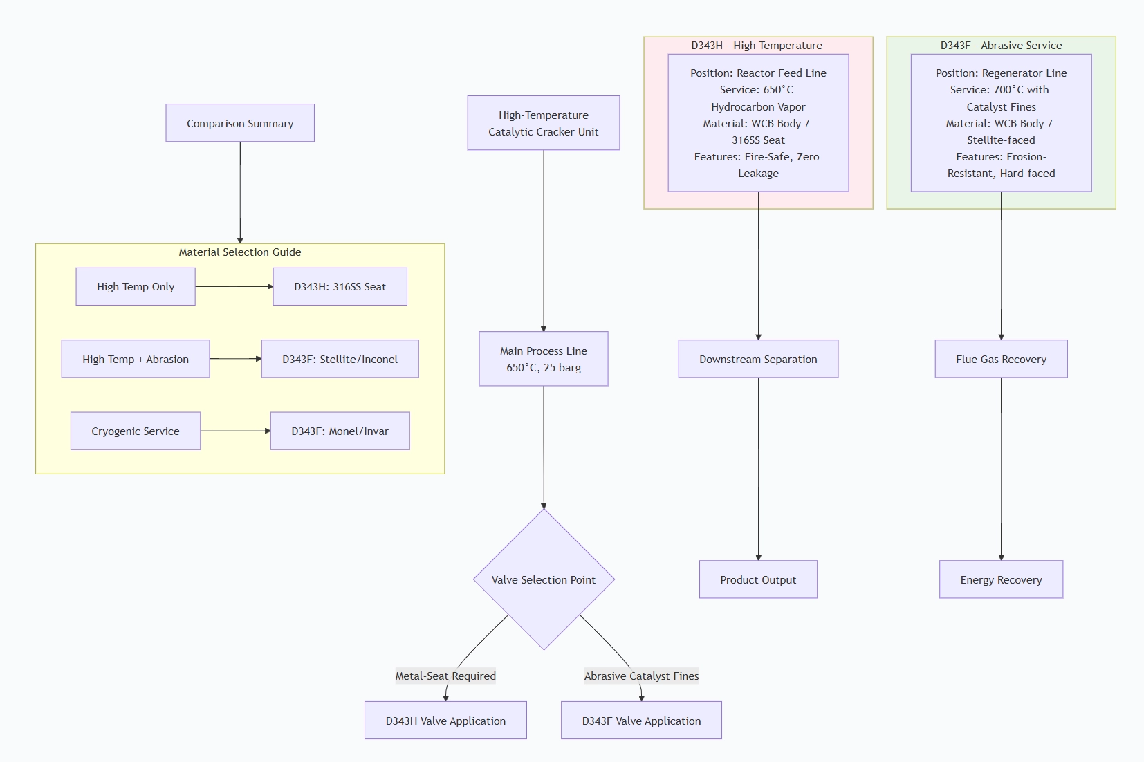
Critical Application Industries:
| Industry | Specific Application | Valve Selection Rationale |
| Oil & Gas Refining | FCCU, Coker, Reformer units | Withstands 400-800°C temperatures, catalyst abrasion |
| Petrochemical | Ethylene cracker, steam cracking | Thermal cycling capability, zero leakage |
| Power Generation | Main steam, turbine bypass | High-pressure steam (Class 600-1500), fire safety |
| Chemical Processing | High-temperature reactors | Corrosion resistance to acids/alkalis |
| LNG & Cryogenics | LNG loading, cryogenic storage | Low-temperature embrittlement resistance |
| Steel & Metals | Coke oven gas, blast furnace | Abrasive dust handling, high temperatures |
Flanged Metal-seat Butterfly Valve D343HD343F Standards: Materials, Design, and Connections
3.1 Material Standards
| Component | D343H Standards | D343F Standards |
| Body & Disc | ASTM A216 WCB, A351 CF8 | ASTM A217 WC6/WC9, A351 CF8M |
| Seat Ring | ASTM A182 F304/F316 | AWS A5.13 Co-Cr alloys, ASTM B564 Inconel |
| Stem | ASTM A564 630 (17-4PH) | ASTM A564 660 (Inconel 718) |
| Hard-facing | - | AWS ERCoCr-A (Stellite 6), Tungsten Carbide |
| Fasteners | ASTM A193 B7/B16 | ASTM A193 B8M, A320 L7/L43 |
3.2 Butterfly Valve for Water Design Standards
| Standard | Title | Application |
| API 609 | Butterfly Valves: Double Flanged, Lug- and Wafer-Type | Primary design standard |
| API 607 | Fire Test for Quarter-Turn Valves | Fire-safe certification |
| API 6FA | Fire Test for Valves | More rigorous fire testing |
| ISO 17292 | Metal butterfly valves | International design standard |
| MSS SP-68 | High Pressure Butterfly Valves | High-pressure applications |
| ASME B16.34 | Valve Design | Pressure-temperature ratings |
3.3 Connection Standards
| Flange Standard | Pressure Classes | Face Type | Application |
| ASME B16.5 | Class 150-600 | RF, RTJ | General process industry |
| ASME B16.47 | Class 75-900 | RF, RTJ | Large diameter pipelines |
| EN 1092-1 | PN10-PN100 | Type 11, 13, 14 | European/international |
| JIS B2220 | 5K-20K | RF | Asian markets |
| ISO 7005-1 | Multiple | RF | Global projects |
Face-to-Face Dimensions: API 609 Table 2 / ISO 5752 Series 20
How to Select Flanged Metal-seat Butterfly Valve D343HD343F
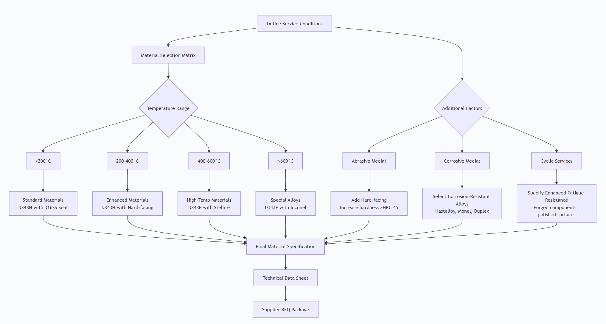
4.1 Technical Specification Development
4.2 Fire protection water supply Critical Specification Elements
Service Conditions (Must Specify):
- Fluid: Composition, phase, abrasives content, corrosion factors
- Temperature: Min/operating/max, thermal cycling rate
- Pressure: Operating/design/test, pressure surges
- Cycling: Frequency (cycles/year), emergency shutdown requirements
- Environmental: Ambient conditions, hazardous area classification
Performance Requirements:
- Leakage Class: ANSI/FCI 70-2 Class IV/V/VI or zero leakage
- Fire Test: API 607 (30 min) or API 6FA (30 min)
- Fugitive Emissions: ISO 15848-1 (Class AH/BH) or TA-Luft
- Cycle Life: Minimum guaranteed cycles (e.g., 50,000 full cycles)
- Operation Torque: Maximum allowable operating/breakaway torque
Material Selection Guide:
| Service Condition | Recommended Seat Material | Hard-facing Required | Notes |
| High Temperature Steam | 316SS, 17-4PH | Yes (Stellite 6) | For >400°C service |
| Abrasive Catalyst | Stellite 21 | Yes (WC-Co) | HRC >55 for severe abrasion |
| Corrosive Chemicals | Inconel 625, Hastelloy C | Optional | CRA (Corrosion Resistant Alloy) |
| Cryogenic LNG | Monel, Invar 36 | No | Low temp impact resistance |
| Sour Service (H2S) | 316SS with NACE | Yes | NACE MR0175/ISO 15156 compliant |
4.3 Fire Protection System Supplier Qualification Process
Step 1: Technical Capability Assessment
- Review design calculations and FEA reports
- Verify manufacturing facilities for precision machining
- Check hard-facing capabilities (automated welding equipment)
- Assess testing facilities (high-pressure, high-temperature testing)
Step 2: Quality System Verification
- Mandatory Certifications: API Q1, ISO 9001
- Special Certifications: API 6D, PED 2014/68/EU (Category IV if needed)
- NDT Capabilities: UT, RT, PT, MPI with certified personnel
- Traceability: Full material traceability from melt to final assembly
Step 3: Performance History Review
- Request minimum 3 references for similar service
- Review failure reports and corrective actions
- Verify experience with your specific service conditions
4.4 Commercial Evaluation Factors
| Factor | Weight | Evaluation Criteria |
| Technical Compliance | 35% | Meets all specifications, certified designs |
| Quality & Reliability | 25% | Track record, warranty terms, failure rates |
| Total Cost of Ownership | 20% | Initial cost + maintenance + expected lifecycle |
| Delivery & Flexibility | 15% | Lead time, responsiveness to changes |
| Technical Support | 5% | Engineering support, documentation quality |
Pre-Shipment Inspection for Export Flanged Metal-seat Butterfly Valve D343HD343F and Key Considerations
5.1 Comprehensive Inspection Protocol
Phase 1: Documentation Review
REQUIRED DOCUMENTS CHECKLIST:
✓ Material Certificates (EN 10204 3.1/3.2)
✓ Heat Treatment Charts
✓ NDT Reports (UT, RT, PT, MPI)
✓ Hardness Test Reports
✓ Dimensional Inspection Reports
✓ Pressure Test Certificates
✓ Fire Test Certificates (API 607/6FA)
✓ Third-Party Inspection Reports
✓ Final Data Book with all records
Phase 2: Visual Inspection
| Inspection Area | Acceptance Criteria | Tools/Methods |
| Surface Finish | Ra ≤ 3.2 μm on sealing surfaces | Surface roughness tester |
| Hard-facing Quality | No cracks, uniform thickness | Dye penetrant, visual |
| Markings | Permanent, per MSS SP-25 | Visual verification |
| Coating/Painting | Uniform, specified thickness | Coating thickness gauge |
| Assembly Quality | Clean, no foreign material | Internal borescope inspection |
Phase 3: Dimensional Verification
Critical Dimensions:
- Seat cone angle: ±0.25° tolerance
- Eccentricity dimensions: ±0.1mm tolerance
- Face-to-face: Per API 609 Table 2
- Flange dimensions: Per specified standard
- Measurement Tools: CMM, height gauges, precision protractors
Phase 4: Material Verification
- Positive Material Identification (PMI): XRF analyzer for alloy verification
- Hardness Testing: Brinell/Rockwell at multiple locations
- Hard-facing Thickness: Ultrasonic thickness gauge
Phase 5: Performance Testing
Pressure Testing (Per API 598):
SHELL TEST:
- Pressure: 1.5 × PN rating
- Medium: Water
- Duration: Minimum per API 598 (based on size)
- Acceptance: No visible leakage, no permanent deformation
SEAT TEST:
- Low Pressure: Air at 0.6 MPa, soap bubble test (zero bubbles)
- High Pressure: 1.1 × PN, both directions
- High-Pressure Gas Test: Optional, for critical service
Operational Testing:
- Torque Test: Measure opening/closing torque vs. angle
- Cycle Test: 3-5 complete cycles minimum
- Limit Switch Test: Verify open/close position accuracy
- Stem Seal Test: Fugitive emission test if specified
Special Testing (If Specified):
- Fire Test Simulation: Verify metal-to-metal contact after soft seal removal
- Cryogenic Test: For LNG applications (-196°C)
- High-Temperature Test: Operational test at elevated temperature
5.2 Special Considerations for Metal-Seated Valves
Seat Lapping Verification:
- Contact pattern ≥85% of seat width
- Uniform contact around entire circumference
- No gaps or discontinuities
Hard-facing Quality Control:
- No porosity or inclusions (per AWS standards)
- Minimum hardness: HRC 40 for Stellite, HRC 55 for tungsten carbide
- Bond strength: No delamination during bend tests
Thermal Distortion Check:
- Verify disc/seat clearance at room and elevated temperatures
- Ensure no binding during thermal cycling simulation
5.3 Export Preparation Protocol
Cleaning & Preservation:
- Complete Internal Cleaning: Remove all machining debris
- Degreasing: Remove all oils and contaminants
- Drying: Complete moisture removal after hydrotest
- VCI Application: Volatile Corrosion Inhibitor application
- Desiccant Placement: Calculate based on internal volume
- Desiccant Quantity (g) = Internal Volume (L) × 20
Protective Packaging:
For Machined Surfaces:
- Flange faces: 3mm plastic/metal covers bolted in place
- Stem ends: Plastic caps with retaining chains
- Actuator mounting: Protective covers
Internal Protection:
- Disc secured in 10-15° open position to prevent seat galling
- VCI emitters placed inside valve body
- Moisture indicators visible through inspection ports
External Crating:
- Wooden Crates: ISPM-15 compliant, 15mm minimum thickness
- Internal Blocking: Prevent movement during transit
- Weather Protection: Polyethylene lining for moisture barrier
- Lifting Points: Clearly marked, rated for valve weight
Marking Requirements:
Crate Marking (All Four Sides):
[CONSIGNEE]
[PROJECT NAME]
[VALVE SERIAL NUMBER]
[GROSS WEIGHT: XXX kg]
[NET WEIGHT: XXX kg]
[DIMENSIONS: L×W×H]
[HANDLING SYMBOLS]
[CENTER OF GRAVITY]
Valve Body Marking (Per MSS SP-25):
Manufacturer's name/trademark
Pressure class designation
Material designation
Temperature rating
Directional arrow (if applicable)
Serial number
Heat numbers for pressure parts
Documentation Package:
Shipping Documents:
Commercial Invoice (3 copies)
Packing List (detailed, per crate)
Bill of Lading/Air Waybill
Certificate of Origin
Insurance Certificate
Export Declaration
Technical Documents (Waterproof Pouch):
Data Book containing:
Manufacturing Data Report
Material Certificates (EN 10204 3.1)
NDT Reports
Test Reports (pressure, functional)
Inspection Release Certificate
Certificates:
API Monogram Certificate
Fire Test Certificate (if applicable)
CE Declaration of Conformity
NACE Compliance Certificate
User Documentation:
Installation, Operation, Maintenance Manual
Spare Parts List with drawings
Recommended Maintenance Schedule
5.4 Third-Party Inspection Requirements
For Critical Service Valves:
Inspection Agency: DNV, BV, SGS, Lloyd's Register
Witness Points (Typical):
Final assembly and dimensional check
Pressure testing (shell and seat)
Functional testing
Preservation and packing
Hold Points:
Material certification review
NDT completion
Final documentation review
Inspection Release Certificate Must Include:
Inspector's name and qualifications
Dates of inspection activities
List of witnessed tests
Non-conformities and resolutions
Final release statement
5.5 Common Defects to Prevent
| Defect | Prevention Method | Detection Method |
| Seat Galling | Proper lubrication during assembly, correct materials | Torque monitoring, visual inspection |
| Hard-facing Cracks | Preheat/interpass temp control, proper weld procedure | Dye penetrant testing, UT |
| Dimensional Errors | CMM verification, first article inspection | Precision measurement |
| Cleaning Issues | Multi-stage cleaning process | White glove inspection, borescope |
| Preservation Failures | Proper VCI application, desiccant calculation | Humidity indicator monitoring |
5.6 Final Release Checklist
Before shipping authorization:
All tests completed and documented
Non-conformities closed with evidence
Documentation package complete and accurate
Preservation and packaging verified
Marking and labeling correct
Weight and dimensions recorded
Shipping documents prepared
Insurance arranged
Carrier instructions provided
Final photographic record completed
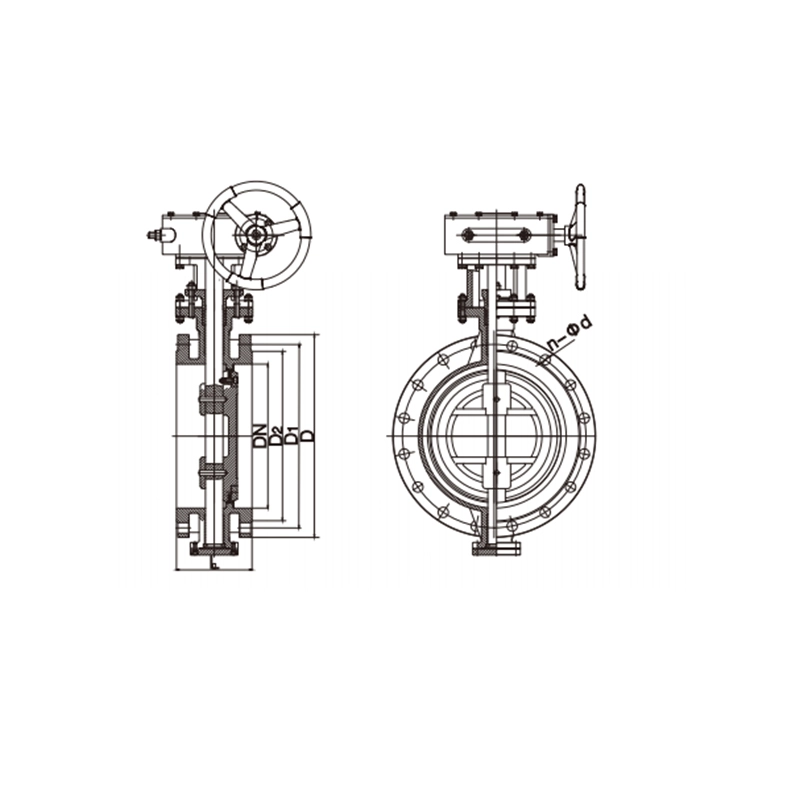
Flanged Metal-seat Butterfly Valve D343HD343F Main dimensions(mm)
| DN | L | Flanged Size and Bolting Specification | |||||||
| 1.6Mpa | 2.5MPa | ||||||||
| D | D1 | D2 | N -Ф d | D | D1 | D2 | N -Ф d | ||
| 50 | 108 | 165 | 125 | 102 | 4-Ф18 | 165 | 125 | 102 | 4-Ф18 |
| 65 | 112 | 185 | 145 | 122 | 8-Ф18 | 185 | 145 | 120 | 8-Ф18 |
| 80 | 114 | 200 | 160 | 138 | 8-Ф18 | 200 | 160 | 135 | 8-Ф18 |
| 100 | 127 | 220 | 180 | 158 | 8-Ф18 | 235 | 190 | 160 | 8-Ф22 |
| 125 | 140 | 250 | 210 | 188 | 8-Ф18 | 270 | 220 | 188 | 8-Ф26 |
| 150 | 140 | 285 | 240 | 212 | 8-Ф22 | 300 | 250 | 218 | 8-Ф26 |
| 200 | 152 | 340 | 295 | 268 | 12-Ф22 | 360 | 310 | 278 | 12-Ф26 |
| 250 | 165 | 405 | 355 | 320 | 12-Ф26 | 425 | 370 | 335 | 12-Ф30 |
| 300 | 178 | 460 | 410 | 378 | 12-Ф26 | 485 | 430 | 395 | 16-Ф30 |
| 350 | 190 | 520 | 470 | 438 | 16-Ф30 | 555 | 490 | 450 | 16-Ф33 |
| 400 | 216 | 580 | 525 | 490 | 16-Ф30 | 620 | 550 | 505 | 16-Ф36 |
| 450 | 222 | 640 | 585 | 550 | 20-Ф30 | 670 | 600 | 555 | 20-Ф36 |
| 500 | 229 | 715 | 650 | 610 | 20-Ф33 | 730 | 660 | 615 | 20-Ф36 |
| 600 | 267 | 840 | 770 | 725 | 20-Ф36 | 845 | 770 | 720 | 20-Ф39 |
| 700 | 292 | 910 | 840 | 795 | 24-Ф36 | 960 | 875 | 820 | 24-Ф42 |
| 800 | 318 | 1025 | 950 | 900 | 24-Ф39 | 1085 | 990 | 930 | 24-Ф48 |
| 900 | 330 | 1125 | 1050 | 1000 | 28-Ф39 | 1185 | 1090 | 1030 | 28-Ф48 |
| 1000 | 410 | 1255 | 1170 | 1115 | 28-Ф42 | 1320 | 1210 | 1140 | 28-Ф56 |
| 1200 | 470 | 1485 | 1390 | 1330 | 32-Ф48 | 1530 | 1420 | 1350 | 32-Ф56 |
| 1400 | 530 | 1685 | 1590 | 1530 | 36-Ф48 | 1755 | 1640 | 1560 | 36-Ф62 |
| 1600 | 600 | 1930 | 1820 | 1750 | 40-Ф56 | 1975 | 1860 | 1780 | 40-Ф62 |
| 1800 | 670 | 2130 | 2020 | 1950 | 44-Ф56 | 2195 | 2070 | 1985 | 44-Ф70 |
| 2000 | 760 | 2345 | 2230 | 2150 | 48-Ф62 | 2425 | 2300 | 2210 | 48-Ф70 |
Note:1. Other specifications and flange standards are available upon request.
2.Design and specifications are subject to change without prior notice