.png)
.png)


Grooved Butterfly Valve with Lever Handle
Grooved Butterfly Valve with Lever Handle Definition and Components
A Grooved Butterfly Valve with Lever Handle Model No. D81X is a versatile, general-purpose quarter-turn valve designed for quick installation and maintenance in a wide range of liquid and gas services. The model number "D81X" is a common industry designation where "D" signifies a butterfly valve, "8" often indicates a grooved-end body style, and "1X" denotes a resilient-seated design with a lever actuator.
Butterfly Valve Fire Protection Key Terminology:
- Grooved Ends:The valve body features precision-machined circumferential grooves at each port. These grooves accept a grooved coupling (a housing and a rubber gasket), enabling fast, bolted assembly without welding, threading, or flange alignment.
- Lever Handle:Provides simple manual 90° operation with clear visual position indication (lever parallel to pipe = OPEN, perpendicular = CLOSED).
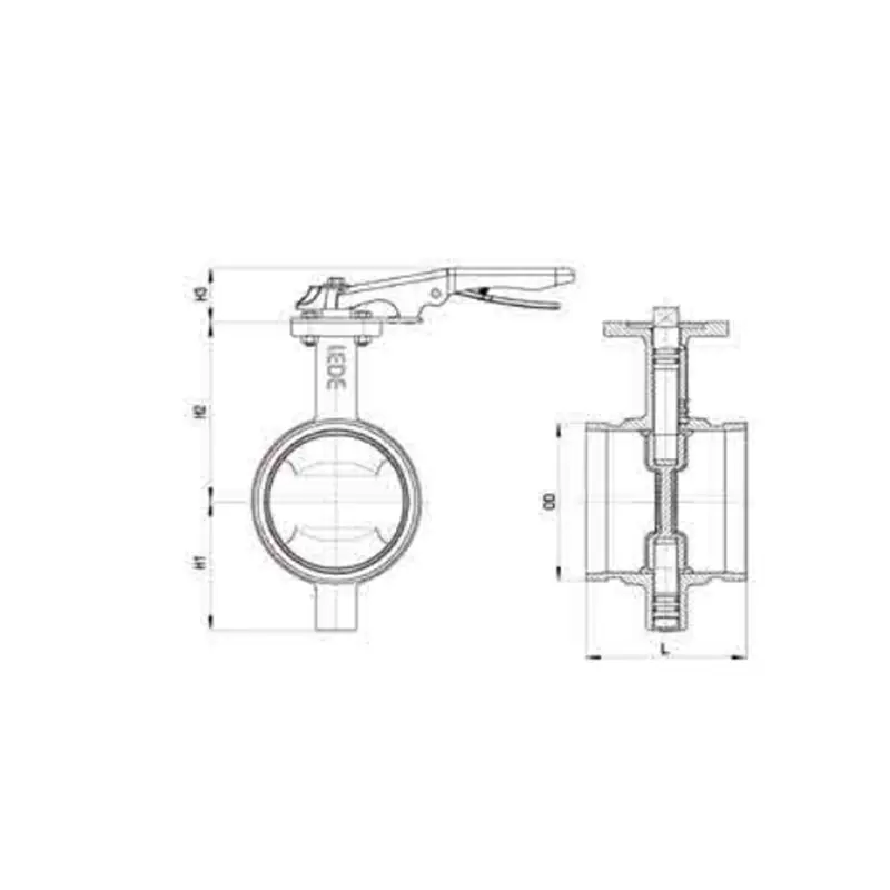
Main Parts:
- Valve Body (Ductile iron or cast iron, with grooved ends)
- Disc (The rotating closure member, typically concentric design)
- Stem (One or two-piece shaft, connecting disc to handle)
- Resilient Seat (Elastomer liner or seat ring, e.g., EPDM, NBR)
- Lever Handle Assembly (Often with a self-limiting stop and provision for a padlock)
- Stem Seals & Bushings (O-rings or packing to prevent stem leakage)
- Grooved End (Machined profile for coupling engagement)
Role, Characteristics, and Application Scenarios of Grooved Butterfly Valve with Lever Handle in Pipelines
Functions:
- On/Off Isolation:Primary function for shutting down sections of a pipeline.
- Throttling/Regulation:Can be used for moderate flow control, though not for precise modulation.
- Bidirectional Service:Effective sealing in both flow directions.
Operational Features:
- Rapid Installation:Grooved couplings significantly reduce installation time compared to flanged or welded connections.
- Quarter-Turn Operation:Quick 90° operation from full open to full closed.
- Space and Weight Efficient:More compact and lighter than equivalent flanged gate valves.
- System Flexibility:Facilitates easy future modifications, additions, or valve replacement.
- Vibration Damping:The rubber gasket in the coupling can absorb some pipe vibration and noise.
Fire Valve Primary Usage Scenarios:
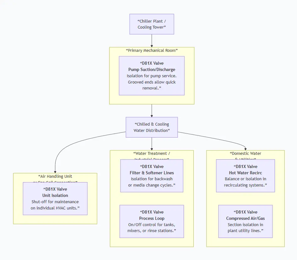
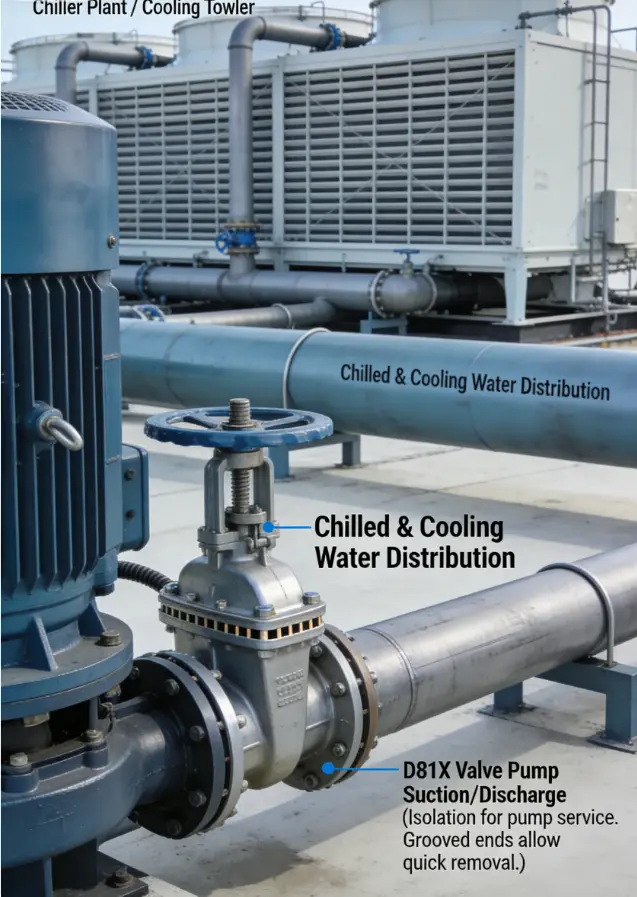
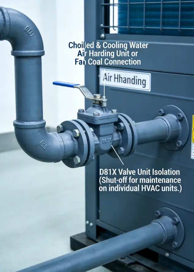
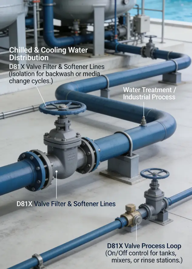
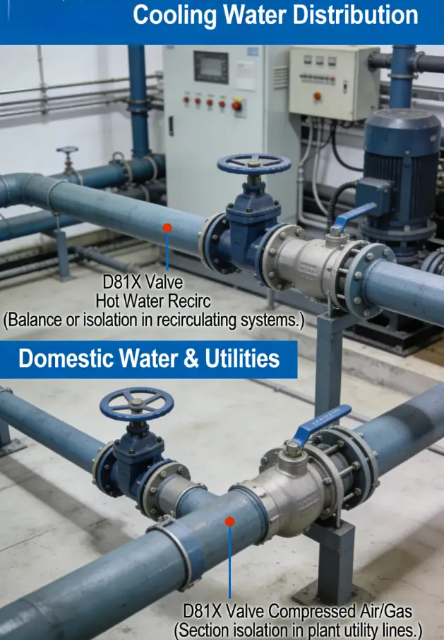
This valve is ideal for commercial, institutional, and industrial systems where installation speed, maintenance ease, and cost-effectiveness are priorities. Common in HVAC, water treatment, industrial process lines, and district energy systems. It is not typically used for fire protection (which requires listed valves like the XD381X) or extreme service conditions.
Scenario Diagram:
Grooved Butterfly Valve with Lever Handle Standards: Materials, Design, and Connections
How to Select Grooved Butterfly Valve with Lever Handle
Step 1: Define Technical Specifications
Clarity is key to ensure compatibility with the existing grooved piping system.
- Service Conditions:Fluid type, maximum temperature (e.g., 80°C for EPDM), and working pressure (e.g., 16 bar/232 psi).
- Size & Connection:Nominal Diameter (e.g., DN150) and Crucially: Groove Specification. State: "Grooved ends to be compatible with [Brand Name, e.g., Victaulic/Viega] Style [e.g., 77] rigid couplings per ANSI/AWWA C606." Provide the required groove O.D. and width if known.
- Materials:Body/disc material (e.g., Ductile Iron), seat elastomer (e.g., EPDM for water), stem material (e.g., SS304).
- Actuator:Lever handle. For sizes above DN200 (8"), specify a gear operator.
- Standards:Reference API 609 or ISO 5752 for design and ANSI/AWWA C606 for grooves.
Step 2: Source and Evaluate Suppliers
- Source from general industrial valve manufacturers or specialized distributors of grooved piping systems.
- Request product data sheets that confirm pressure/temperature ratings, materials, andmost importantly, the specific coupling compatibility.
- Evaluate based on technical match to your groove system, price, and lead time. Brand-name compatibility (e.g., "fits Victaulic") is a major purchasing factor.
Step 3: Order Execution
- These are often semi-standard stock items. Confirm lead times.
- Required documents: Commercial Invoice, Packing List, Certificate of Compliance. Material Test Reports (MTRs) can be requested but may incur extra cost.
Pre-Shipment Inspection for Export Grooved Butterfly Valve with Lever Handle and Key Considerations
Inspection Checklist:
Fire Protection Butterfly Valves Key Precautions for Export:
- Mandatory Groove Protection:The functional integrity of the valve depends on perfect grooves. Use hard, screw-on caps designed for grooved pipe. These are more expensive than simple plugs but prevent damage that would render the valve unusable.
- Packing for Stacking:These valves are often palletized and stacked. Ensure internal packaging (like cardboard dividers) prevents metal-to-metal contact and the levers from interfering with adjacent valves.
- Corrosion Prevention:For carbon steel components, ensure a light, non-sticky anti-rust oil is applied. For long sea voyages, include VCI (Vapor Corrosion Inhibitor) paper in the packaging.
- Clear Identification:Mark each crate/box clearly with size, model number, and quantity. For mixed pallets, include a detailed packing list in a waterproof bag attached to the pallet.
Grooved Butterfly Valve with Lever Handle Size Chart