.png)
.png)


Grooved Butterfly Valve with Tamper Switch
Grooved Butterfly Valve with Tamper Switch Definition and Components
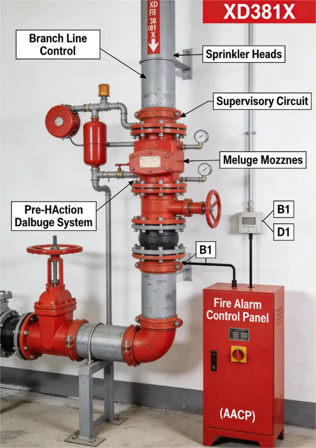
A Grooved Butterfly Valve with Tamper Switch Model No. XD381X is a critical component in fire protection sprinkler systems. It is designed for quick installation using a grooved piping system and includes an integral supervisory device to monitor its position.
Key Terminology:
- Grooved Ends:The valve body features machined circumferential grooves at each end. These grooves accept a pressure-responsive coupling consisting of a housing and a rubber gasket, allowing for fast, boltless assembly and disassembly without welding or threading.
- Tamper Switch (Supervisory Switch):An electrical device mechanically linked to the valve stem. It sends a signal to the Fire Alarm Control Panel (FACP) if the valve is moved from its normal, open position, indicating possible impairment of the fire suppression system.
- Model XD381X:A manufacturer's designation where "XD" often signifies a fire protection valve, "38" indicates a grooved-end butterfly valve, and "1X" denotes a specific series with a resilient seat and lever/gear actuator.
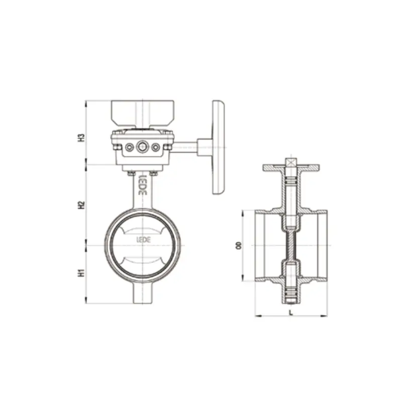
Fire Sprinkler Butterfly Valve Main Parts:
- Valve Body (Ductile iron, with grooved ends)
- Disc (Often a lugged or eccentric design for better sealing, epoxy-coated)
- Stem (Stainless steel, connects disc to actuator)
- Resilient Seat (Elastomer like EPDM, creates a bubble-tight seal)
- Actuator (Lever handle or gear operator)
Tamper Switch Assembly:
- Weatherproof Enclosure (NEMA 4X)
- Actuating Cam mounted on the stem
- Sealed Micro-Switch (SPDT typical)
- Conduit Entry
- Grooved End (Precisely machined for coupling engagement)
Role, Characteristics, and Application Scenarios of Grooved Butterfly Valve with Tamper Switch in Pipelines
Fire Valve Functions:
- System Isolation:Provides a shut-off point for sections of a fire sprinkler system.
- Supervisory Monitoring:Continuously reports the valve's open/closed status to a central alarm panel as required by fire codes (e.g., NFPA 13, NFPA 72).
- Alarm Initiation:Generates a "supervisory" or "trouble" signal upon unauthorized operation, alerting building personnel.
Operational Features:
- Fast Installation/Modification:Grooved connections allow for quick assembly and future system modifications without hot work.
- Quarter-Turn Operation:Lever or gear operator allows for rapid opening and closing.
- Visual & Electrical Indication:Lever position gives local visual status; tamper switch provides remote electrical status.
- Vibration/Absorption:The rubber-gasketed grooved coupling can dampen vibration and accommodate minor pipe movement.
Fire Protection Butterfly Valves Primary Usage Scenarios:
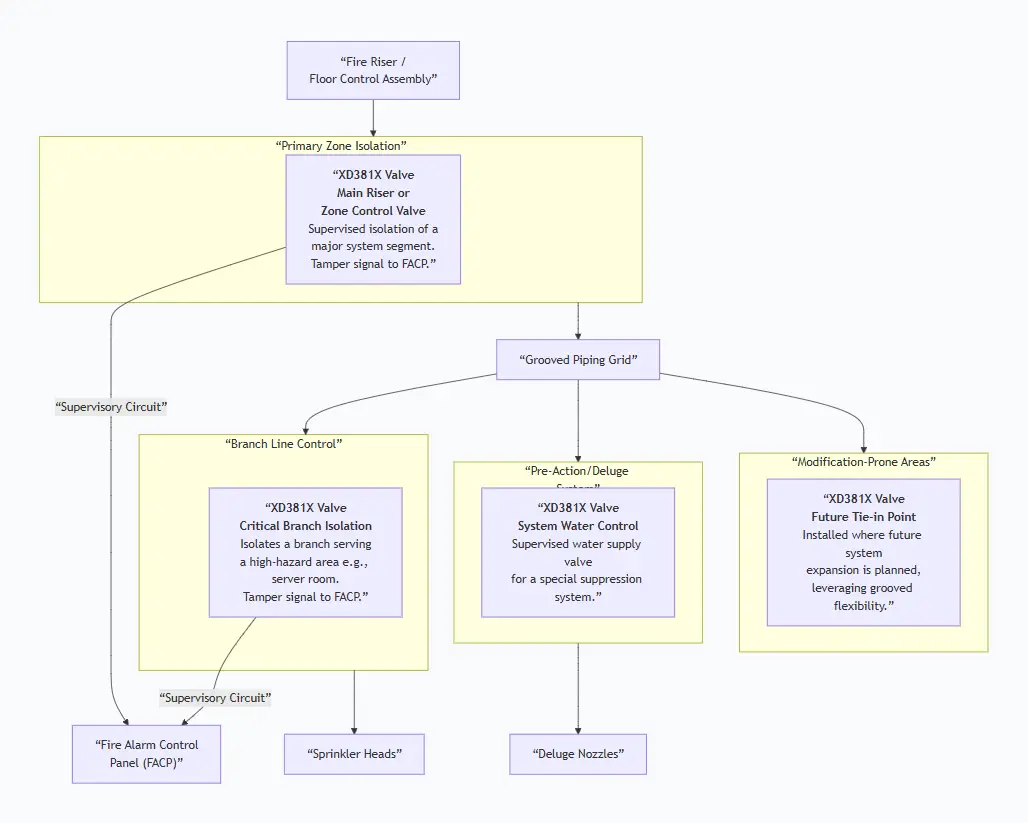
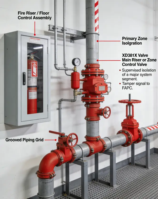
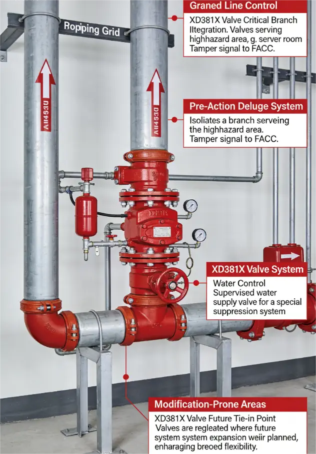
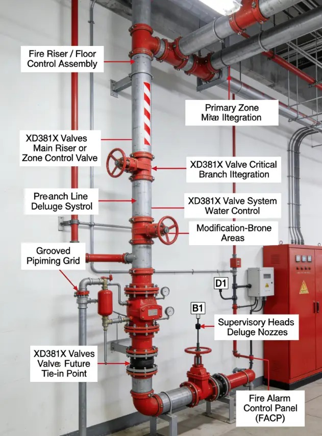
This valve is mandated in supervised fire sprinkler systems, especially in buildings where piping modifications are anticipated or where installation speed is critical (e.g., data centers, hospitals, high-rises).
Scenario Diagram:
Grooved Butterfly Valve with Tamper Switch Standards: Materials, Design, and Connections
How to Select Grooved Butterfly Valve with Tamper Switch
Step 1: Define Rigorous Specifications
Fire protection valves require precise specifications:
- Listing & Code Compliance:State: "Valve must be UL 1091 Listed and/or FM Approved for fire protection service. Model must be as shown on UL/FM's published list."
- Size, Pressure, & Ends:Nominal Diameter (e.g., 6"), Pressure Rating (e.g., 175 psi, 300 psi), and Groove Specification (e.g., "For use with Style ___ grooved couplings per ANSI/AWWA C606").
- Materials & Construction:Ductile iron body, epoxy-coated disc (per UL/FM), EPDM seat, stainless steel stem.
- Tamper Switch:Specify electrical ratings (voltage, current, NO/NC contacts), conduit size, and enclosure rating (NEMA 4X).
- Actuator:Lever with padlock lugs or gear operator for larger sizes.
Step 2: Source from Qualified, Specialized Suppliers
- Onlyprocure from suppliers authorized to sell UL/FM listed fire protection products.
- Require a complete submittal packageincluding: UL/FM listing cards, dimensional drawings with groove details, wiring schematic for the switch, and material certifications.
- Verify the entire assembly(valve + switch) is listed together, not as separate components.
Step 3: Pre-Shipment Validation
- For large projects, mandate a Factory Acceptance Test (FAT)to witness pressure testing and switch functionality.
- Confirm packaging will protect the grooved ends and the externally mounted switch.
Pre-Shipment Inspection for Export Grooved Butterfly Valve with Tamper Switch and Key Considerations
Inspection Checklist:
Key Precautions for Export:
- Absolute Groove Protection:The precision-machined grooves are easily damaged. Use hard caps designed for grooved pipe. Consider boxing the valve within a larger crate with ample blocking.
- Switch as a Fragile Component:Treat the entire tamper switch assembly as delicate instrumentation. Pack to prevent any direct impact.
- Desiccant is Mandatory:Include silica gel bags inside the valve body (if possible) and the switch housing to prevent condensation and internal corrosion during sea transit.
- Secure Actuator:Lock or tape the lever in the OPEN position to prevent accidental closure and switch actuation during transit.
- Documentation Pack:Place the UL/FM listing card, test reports, and installation manual in a waterproof pouch inside the crate, not just in the shipping paperwork. This ensures it reaches the installing contractor.
Grooved Butterfly Valve with Tamper Switch Size Chart