.png)
.png)


Grooved Swing Check Valve
Grooved Swing Check Valve Definition and Components
A Grooved Swing Check Valve Model No. H84X is an automatic check valve designed for quick installation in systems utilizing grooved piping. It prevents reverse flow (backflow) and is distinguished by its mechanical coupling ends. The model number decodes as: H (Check Valve), 8 (Grooved Ends), 4 (Swing Disc Design), X (Resilient/Rubber Seat).
Fire Sprinkler Check Valve Key Terminology:
- Grooved Ends:The valve body features precision-machined circumferential grooves that accept a grooved coupling (a housing and a rubber gasket). This allows for boltless, fast, and flexible pipe connections.
- Swing Disc:A hinged disc that swings open in the direction of flow and closes automatically to seal against backflow.
- Resilient Seat:An elastomer (e.g., EPDM, NBR) sealing surface ensures bubble-tight closure and dampens the impact of the disc, reducing water hammer compared to metal seats.
Main Parts:
- Valve Body: The main housing with integrated grooved ends.
- Cover: Provides access to internal components; may be bolted or threaded.
- Disc: The swinging closure member.
- Hinge Pin & Arm Assembly: Allows the disc to pivot freely.
- Resilient Seat Ring: Creates the sealing surface for the disc.
- Grooved Ends: Machined profiles for coupling engagement.
Role, Characteristics, and Application Scenarios of Grooved Swing Check Valve in Pipelines
Fire Check Valve Functions:
- Unidirectional Flow Control:Permits flow in one direction only, automatically preventing reverse flow.
- Equipment Protection:Safeguards pumps, compressors, and other equipment from damage caused by backflow.
- System Integrity:Maintains pressure and prevents contamination in system segments.
Operational Features:
- Fast Installation:Grooved connections significantly reduce installation time compared to flanged or welded valves.
- Automatic Operation:Functions based on flow differential—no external power or manual intervention required.
- Full Flow, Low Resistance:In the open position, the disc swings completely out of the flow path, minimizing pressure drop.
- Horizontal Installation Mandatory:Must be installed with the hinge pin horizontal for proper gravity-assisted closure. Not for vertical flow unless specifically designed.
- Slam Potential:Can experience disc slam upon sudden flow reversal. For critical prevention of water hammer, a spring-assisted "non-slam" check valve is recommended.
- Primary Usage Scenarios:
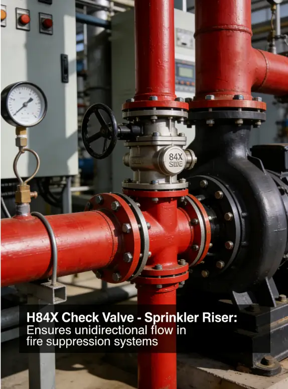
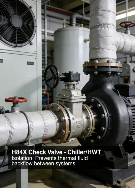
Ideal for commercial, industrial, and fire protection systems where installation speed, ease of maintenance, and system modularity are valued. Common in HVAC, process water, and fire sprinkler lines.
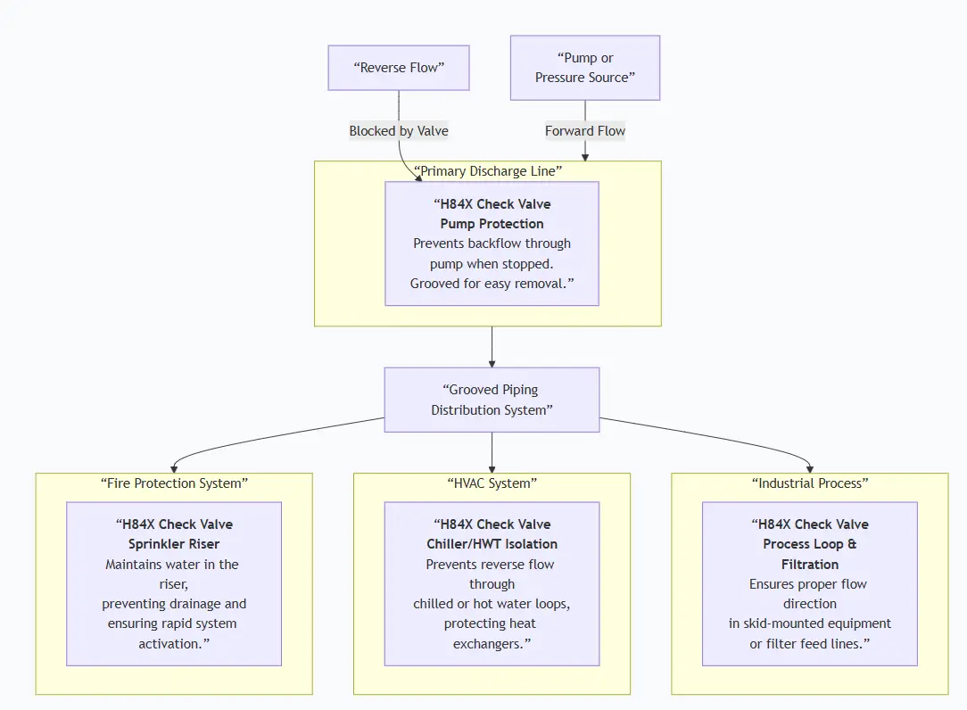
Scenario Diagram:

Grooved Swing Check Valve Standards: Materials, Design, and Connections
| Standard Type | Primary Standard(s) | Purpose & Key Specifications |
| Design & Dimensions | API 594 / AWWA C508 | API 594 covers check valve design broadly. AWWA C508 is the specific standard for Resilient-Seated, Grooved-End Swing Check Valves for waterworks service, defining design, performance, and materials. |
| Grooved Connection | ANSI/AWWA C606 / UL 603 (Fire) | ANSI/AWWA C606 is the key standard for Grooved and Shouldered Joints. UL 603 applies to couplings for fire protection service. |
| Fire Protection Listing | UL 312 / FM 1120 | For valves used in fire sprinkler systems. UL 312 is the standard for Check Valves for Fire-Protection Service. |
| Material Standards | ASTM A536 (Ductile Iron Body) | Common material specifications. Seats often comply with NSF/ANSI 61 for potable water. |
| ASTM A276 (Stainless Steel Stem/Hinge Pin) | ||
| ASTM D2000 (Elastomer for Seat) | ||
| Testing | API 598 / AWWA C508 | Defines shell and seat pressure test procedures and acceptable leakage rates. |
How to Select Grooved Swing Check Valve
Step 1: Define Technical Specifications
Clarity on groove compatibility is essential.
- Service Conditions:Fluid, temperature, pressure (e.g., 150 psi, 16 bar).
- Size & Connection:Nominal Diameter (e.g., 6") and Groove Specification. State: "Grooved ends to be compatible with [Coupling Brand, e.g., Victaulic] Style [e.g., 77], per ANSI/AWWA C606."
- Materials:Body (e.g., Ductile Iron), Seat Elastomer (e.g., EPDM for water), Trim (e.g., SS304).
- Standards & Listing:For general service: AWWA C508. For fire sprinklers: Must be UL 312 Listed or FM Approved.
- Special Needs:Note if a spring kit or external lever is needed for vertical installation or flow control.
Step 2: Source and Evaluate Suppliers
- Source from manufacturers specializing in grooved piping products or general valve suppliers with grooved line expertise.
- Request submittals including: Dimensional drawings highlighting groove details, pressure rating charts, and compatibility documentationwith specific coupling brands.
- For fire service, non-negotiableproof of UL/FM listing for the exact model is required.
Step 3: Order Execution
- Confirm lead times. Grooved valves are often stock items.
- Required documents: Commercial Invoice, Packing List, Certificate of Compliance, and Material Test Reports (MTRs)for body/disc. For listed valves, include the UL/FM Guide Card.
Pre-Shipment Inspection for Export Grooved Swing Check Valve and Key Considerations
Fire Fighting Valve Inspection Checklist:
| Category | Check Point | Acceptance Criteria |
| Documentation | 1. Compliance Certificates | AWWA C508 or UL/FM listing proof as specified. |
| 2. Material Test Reports | MTRs for body and major components. | |
| 3. Test Certificate | Shell and seat pressure test report. | |
| Physical/Functional | 4. Groove Inspection | CRITICAL: Grooves must be clean, smooth, with no burrs, cracks, or machining defects. Verify with a sample coupling if possible. |
| 5. Disc Movement | Disc must swing freely and silently on its hinge. No sticking or grinding. | |
| 6. Seat Condition | Resilient seat must be intact, without cuts, tears, or permanent deformation. | |
| 7. Marking | Body must be marked with size, pressure rating, material, and flow direction arrow. | |
| Packaging | 8. Groove End Protection | Must have threaded, rigid plastic or metal protective caps designed for grooved pipe. |
| 9. Disc Securement | Disc must be blocked or strapped in the CLOSED position to prevent damaging swing during transit. |
Key Precautions for Export:
- Absolute Groove Protection:The valve's functionality depends on perfect grooves. Use manufacturer-supplied, screw-on hard caps. Never ship with only plastic wrap or tape over the ends.
- Immobilize Internals:Securing the disc is mandatory to prevent hinge damage and seat wear from constant bouncing.
- Moisture Prevention:For sea freight, include desiccant (silica gel) bags within the valve body and the packaging to prevent internal corrosion.
- Reinforced Packaging:Due to the protruding grooved ends, pack valves individually or with ample spacing and cushioning in the crate to prevent impact damage.
- Documentation Inclusion:Place a waterproof pouch containing the test reports, compatibility guide, and installation manual inside the shipping crate.
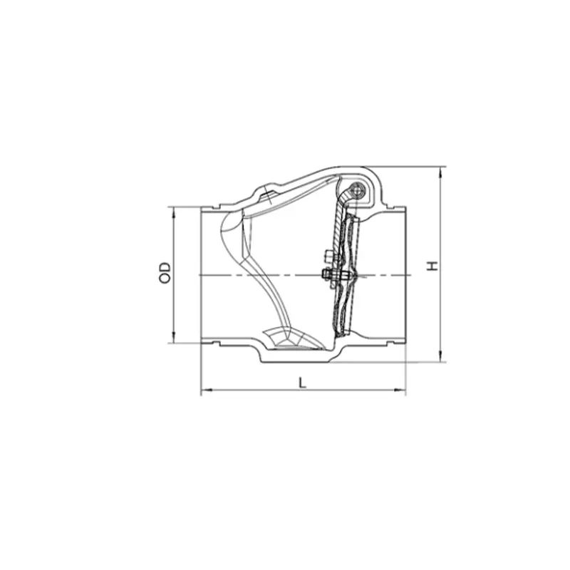
Grooved Swing Check Valve Size Chart