.png)
.png)


Non-rising Resilient Seat Gate Valve
Non-rising Resilient Seat Gate Valve Purpose
This valve is mounted on various pipelines and used as a bi-way closed circuit equipment for tap water, sewage treatment, metallurgy, petroleum, building, chemical, electric
industries etc.
Non-rising Resilient Seat Gate Valve Definition and Components
1.1 What is a Z45X Non-rising Resilient Seat Gate Valve?
Z45X is a standardized Chinese designation for a specific type of gate valve:
Z: Gate Valve
4: Connection Type - Flanged
5: Structure Type - Non-rising Stem
X: Seat Material - Resilient (Rubber) Seat
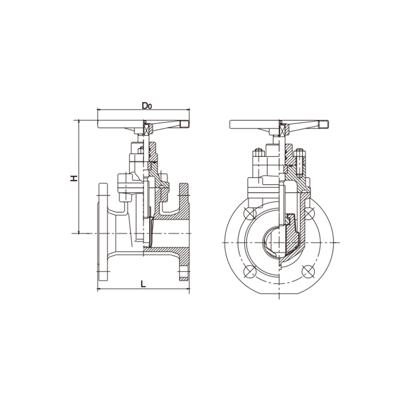
This is a non-rising stem, flanged, resilient-seated gate valve that features a fully encapsulated rubber-coated gate and an internal stem mechanism where the stem does not move upward when operated. Instead, the gate rises internally while the handwheel and stem nut move vertically within the valve body.
1.2Non-rising Resilient Seat Gate Valve Main Components
| Component | Material/Type | Critical Function | Special Features |
| 1. Valve Body | Ductile Iron (QT450-10), Cast Iron (HT250), Cast Steel (WCB) | Main pressure-retaining component with flow passage | Compact design, integral flanges |
| 2. Resilient Gate | Cast Iron/Steel core +Full Rubber Encapsulation(EPDM/NBR) | Primary sealing element with elastic surface | Bubble-tight sealing, corrosion-resistant coating |
| 3. Non-rising Stem | Stainless Steel (2Cr13, 304SS) | Transmits rotational motion to linear gate movement | Threads inside valve body, stem position fixed |
| 4. Stem Nut (Yoke Bush) | Bronze/Copper Alloy or Stainless Steel | Converts rotary to linear motion | Self-lubricating, wear-resistant |
| 5. Body Seat Rings | Ductile Iron/Stainless Steel with machined surfaces | Provides sealing surface for rubber gate | Replaceable in some designs |
| 6. Stem Seal/Packing | PTFE/V-ring packing or O-ring seals | Prevents leakage along stem | Adjustable packing gland |
| 7. Handwheel/Operator | Cast iron with epoxy coating | Manual operation interface | Fixed position, ergonomic design |
| 8. Bonnet/Yoke Assembly | Same as body material | Encloses stem mechanism | Bolted or pressure-sealed design |
Role, Characteristics, and Application Scenarios of Non-rising Resilient Seat Gate Valve in Pipelines
2.1 Pipeline Functions
Full Flow Isolation: Provides straight-through flow with minimal pressure drop when open
Bubble-tight Shutoff: Achieves zero-leakage closure in both directions
Space-efficient Operation: Non-rising stem design saves vertical space
Low Maintenance: Resilient seat requires no lubrication or adjustment
Corrosion Protection: Rubber encapsulation protects metal components from corrosive media
2.2 Operational Features
| Feature | Technical Explanation | Operational Benefit |
| Non-rising Stem | Stem rotates but doesn't ascend; gate rises internally | Space-saving - no overhead clearance needed |
| Resilient Sealing | Rubber-to-metal sealing interface | Bubble-tight closure without metal-to-metal contact |
| Low Operating Torque | Rubber compression vs metal friction | Easy manual operation even in large sizes |
| Bi-directional Flow | Symmetrical gate and seat design | Installation independent of flow direction |
| Full Bore Design | Gate retracts completely into bonnet | Minimal pressure loss when open |
| Maintenance-free Seat | Rubber doesn't require lubrication or adjustment | Reduced lifecycle costs |
2.3 Water Valves Application Scenario Diagram
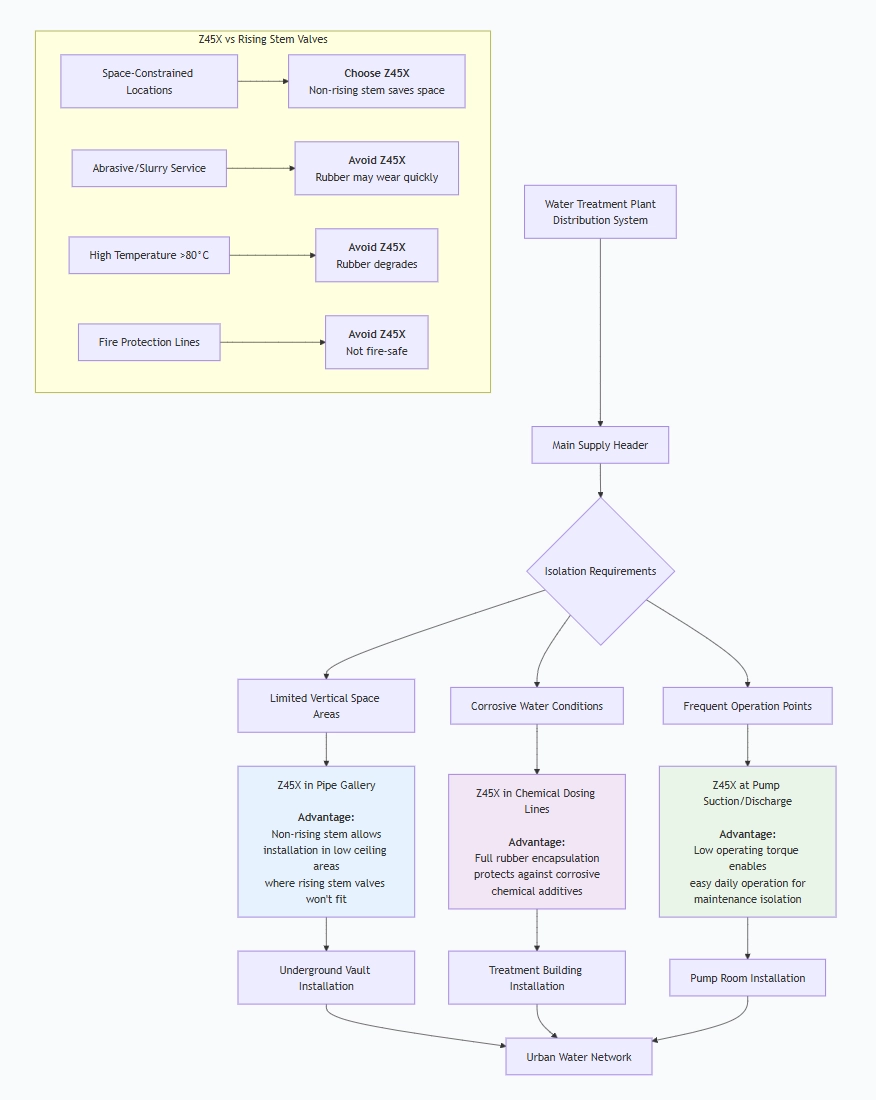
Typical Application Industries:
| Industry | Specific Application | Why Z45X is Suitable |
| Water Supply & Distribution | Main line isolation, branch connections | Bubble-tight seal for potable water, no contamination |
| Wastewater Treatment | Effluent lines, sludge handling | Corrosion resistance to sewage, easy operation |
| Building Services | Basement mechanical rooms, pipe chases | Space-saving design in confined areas |
| Irrigation Systems | Main line control, zone valves | Reliable sealing, minimal pressure loss |
| Industrial Water | Cooling water, process water lines | Low maintenance, durable in continuous service |
| HVAC Systems | Chilled/heating water isolation | Excellent sealing, compact installation |
Non-rising Resilient Seat Gate Valve Standards: Materials, Design, and Connections
1 Gate Valve for Water Material Standards
| Component | Standard | Common Materials |
| Body & Bonnet | ASTM A126 Class B, ASTM A216 WCB | Gray Cast Iron, Ductile Iron QT450-10 |
| Gate | ASTM A48, with rubber encapsulation | Cast Iron + EPDM/NBR/Viton |
| Stem | ASTM A276, ASTM A564 | 304SS, 316SS, 17-4PH |
| Stem Nut | ASTM B584, ASTM B505 | C83600 Bronze, C93200 Bronze |
| Seat Rings | ASTM A126, ASTM A216 | Cast Iron, Ductile Iron, Stainless Steel |
| Bolting | ASTM A193, ASTM A307 | B7, B8, Grade 5 |
| Rubber Components | FDA 21 CFR 177, WRAS, NSF/ANSI 61 | EPDM, NBR, Viton |
3.2 Design Standards
| Standard | Title | Key Requirements |
| API 600 | Steel Gate Valves | Design basis for bolted bonnet valves |
| API 603 | Corrosion-resistant Gate Valves | For severe service applications |
| ISO 5208 | Industrial Valves Pressure Testing | Leakage rate classifications |
| MSS SP-70 | Cast Iron Gate Valves | Design requirements for iron body valves |
| MSS SP-80 | Bronze Gate Valves | Construction standards |
| BS EN 1171 | Industrial Valves - Cast Iron Gate Valves | European standard |
| AWWA C509 | Resilient-seated Gate Valves for Water Supply | Water industry standard |
3.3 Connection Standards
| Flange Standard | Pressure Classes | Face Type | Common Applications |
| ASME B16.1 | Class 125, 250 | Raised Face | Cast Iron flanges (US) |
| EN 1092-2 | PN10, PN16, PN25 | Type A, B1, B2 | Cast Iron flanges (EU) |
| ASME B16.5 | Class 150 | Raised Face | Steel flanges |
| JIS B2220 | 5K, 10K | Raised Face | Japanese standard |
| ISO 7005-2 | PN10-PN25 | Raised Face | International projects |
Face-to-Face Dimensions: Generally comply with ISO 5752 or API 600 Annex A
How to Select Non-rising Resilient Seat Gate Valve
4.1 Technical Specification Development
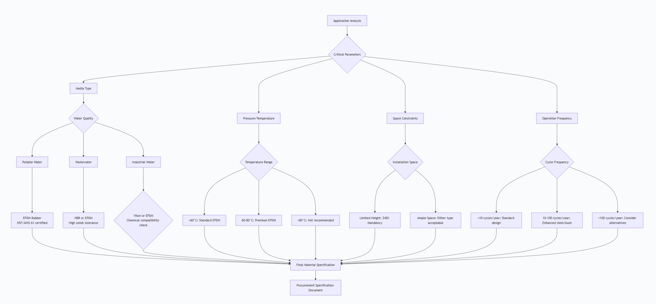
4.2 Critical Specification Elements
- Service Conditions (Must Specify):
Fluid type and characteristics (pH, chlorine content, solids)
Operating pressure and test pressure requirements
Temperature range (minimum, normal, maximum)
Cycling requirements (operations per year)
External environment (buried, submerged, corrosive atmosphere)
- Design Requirements:
Pressure class: PN10, PN16, Class 125, Class 150
End connection type and standard
Face-to-face dimensions
Stem orientation (vertical/horizontal operation)
By-pass requirement (for large diameters)
Position indicator requirement
- Material Selection Guide:
| Service Condition | Body Material | Gate Coating | Stem Material |
| Potable Water | Ductile Iron QT450-10 | EPDM (NSF 61) | 304SS |
| Wastewater | Gray Cast Iron | NBR or EPDM | 316SS |
| Sea Water | Bronze or 316SS | EPDM | 316SS or Monel |
| Industrial Water | Ductile Iron or WCB | EPDM or Viton | 304SS or 17-4PH |
- Special Requirements:
Fire-safe design: Generally NOT available for resilient-seated valves
Cryogenic service: Not recommended (rubber becomes brittle)
Abrasive media: Not recommended (rubber wears quickly)
Steam service: Not suitable (temperature too high)
4.3 Supplier Evaluation Factors
| Evaluation Category | Weight | Key Assessment Criteria |
| Technical Compliance | 30% | Meets all specifications, proper certifications |
| Quality Management | 25% | ISO 9001 certified, testing procedures, quality records |
| Manufacturing Capability | 20% | Production capacity, equipment, technical expertise |
| Delivery Performance | 15% | On-time delivery history, lead time commitments |
| Cost Competitiveness | 10% | Price, payment terms, total cost of ownership |
Certification Requirements:
ISO 9001 Quality Management System
NSF/ANSI 61 for potable water applications
CE Marking for European market
Local approvals (WRAS, UL, FM as required)
4.4 Purchase Documentation
Ensure the purchase order includes:
Complete technical specification sheet
Reference to all applicable standards
Inspection and test requirements (ITP)
Documentation deliverables list
Packaging and marking requirements
Spare parts requirements
Warranty terms and conditions
Pre-Shipment Inspection for Export Non-rising Resilient Seat Gate Valve and Key Considerations
5.1 Comprehensive Inspection Protocol
Phase 1: Documentation Review
REQUIRED DOCUMENTS CHECKLIST:
✓ Material Certificates (EN 10204 3.1 for metallic parts)
✓ Rubber Material Certificates (with FDA/NSF if applicable)
✓ Pressure Test Certificates
✓ Dimensional Inspection Reports
✓ Certificate of Conformity
✓ Operation & Maintenance Manuals
✓ Packing List
Phase 2: Visual and Dimensional Inspection
| Inspection Area | Check Points | Acceptance Criteria |
| External Surface | Casting quality, finish, defects | No cracks, porosity, or defects affecting integrity |
| Flange Faces | Surface finish, scratches, gouges | Smooth, no damage affecting sealing |
| Markings | Identification per MSS SP-25 | Legible, permanent, complete information |
| Dimensions | Face-to-face, flange dimensions | Within tolerance per specified standards |
| Coating | Paint thickness, adhesion, coverage | Per specification, minimum 200渭m DFT |
Phase 3: Material Verification
Positive Material Identification (PMI): Verify alloy composition of stem
Hardness Testing: Check body and critical components
Rubber Testing: Verify durometer hardness (if test samples available)
Phase 4: Pressure Testing (Per API 598/ISO 5208)
SHELL TEST (High Pressure):
- Test Pressure: 1.5 × PN rating
- Medium: Water
- Duration: Minimum per standard (based on size)
- Acceptance: No visible leakage, no permanent deformation
SEAT TEST (Low Pressure):
- Test Pressure: 1.1 × PN rating
- Medium: Air (preferred for bubble detection) or water
- Duration: Minimum per standard
- Acceptance: Zero visible leakage for resilient seats
TEST SEQUENCE:
- Partially open valve (10% open)
- Fill body with test medium
- Apply shell test pressure
- Close valve against pressure
- Release body pressure
- Apply seat test pressure upstream
- Check downstream for leakage
- Repeat for opposite direction
Phase 5: Functional Testing
Operation Test: 3 complete open-close cycles minimum
Torque Measurement: Record maximum operating torque
Stem Seal Test: Check for leakage along stem during/after operation
Position Verification: Ensure full open and full closed positions are achievable
5.2 Special Considerations for Resilient-Seated Gate Valves
- Gate Inspection:
Verify complete rubber encapsulation with no voids or defects
Check for uniform rubber thickness (typically 3-6mm)
Ensure rubber is firmly bonded to metal core
Verify gate edges are properly protected by rubber
- Seat Contact Verification:
Visual inspection of seat surfaces for smooth finish
Check for uniform contact pattern (after pressure test)
Verify no metal-to-metal contact points
- Stem/Stem Nut Engagement:
Check thread engagement throughout full travel
Verify smooth operation without binding
Ensure adequate lubrication on threads (if specified)
5.3 Export Preparation Protocol
- Cleaning and Preservation:
Complete Internal Cleaning: Remove all test water and debris
Drying: Compressed air blow-down to remove moisture
Rust Prevention: Apply VCI (Vapor Corrosion Inhibitor) to internal surfaces
External Protection: Touch-up paint on any damaged coating
Desiccant Placement: For valves > DN200, place desiccant bags inside
- Protective Packaging:
Individual Valve Protection:
Flange Face Protection: 3mm minimum thickness plastic/metal covers bolted in place
Stem Protection: Plastic cap over stem end
Handwheel Protection: Cardboard or foam wrapping
Gate Position: Secure in fully open position to prevent rubber compression set
Internal Protection:
VCI emitter placed inside valve body
Moisture indicator visible through open end
Warning tag: "Remove desiccant before installation"
Crating Requirements (for sea freight):
Wooden Crates: ISPM-15 compliant (heat treated or fumigated)
Internal Blocking: Prevent movement during transit
Weather Protection: Polyethylene lining or waterproof paper
Lifting Points: Clearly marked with safe working load
- Marking and Labeling:
Crate Marking (All sides):
CONSIGNEE: [Name/Address]
SHIP TO: [Site/Project]
VALVE ID: [Tag Number]
PACKAGE: [X of Y]
GROSS WEIGHT: [kg]
NET WEIGHT: [kg]
DIMENSIONS: [L×W×H]
HANDLE WITH CARE
KEEP DRY
THIS SIDE UP
Valve Body Marking (Per MSS SP-25):
Manufacturer's name or trademark
Pressure class designation (PN or Class)
Material designation
Size (DN and NPS)
Directional flow arrow (if applicable)
Heat number (for steel valves)
- Documentation Package:
Shipping Documents:
Commercial Invoice (3 copies)
Packing List (detailed per crate)
Bill of Lading / Air Waybill
Certificate of Origin
Insurance Certificate
Export Declaration
Technical Documents (Waterproof envelope inside crate):
Test and Inspection Reports:
Material Test Certificates
Pressure Test Certificates
Final Inspection Report
Certificates:
Certificate of Conformity
NSF/ANSI 61 Certificate (if applicable)
CE Declaration of Conformity (if applicable)
User Documentation:
Installation Instructions
Operation and Maintenance Manual
Spare Parts List
Warranty Certificate
5.4 Special Precautions for Resilient-Seated Valves
- Temperature Considerations:
Store in temperature-controlled environment if possible
Avoid exposure to direct sunlight for extended periods
Temperature range during storage: -10°C to +40°C
- Rubber Protection:
Protect from ozone, oils, and solvents
Avoid compression of rubber gate during storage
Ensure rubber components are not in contact with VCI materials that may degrade rubber
- Long-term Storage:
For storage >6 months, partially exercise valve quarterly
Check desiccant condition monthly
Maintain proper ventilation in storage area
5.5 Final Inspection Checklist
Before Crate Closure:
All protective covers in place and secured
Valve secured in fully open position
Desiccant and moisture indicator placed
VCI emitter activated (if used)
Internal inspection completed and documented
All accessories included (bolts, gaskets if specified)
Before Shipment Release:
All test certificates verified and included
Documentation package complete
Markings clear and correct
Weight and dimensions recorded
Crating secure and weatherproof
Shipping documents prepared
Insurance arranged
5.6 Common Issues to Prevent
| Potential Issue | Preventive Action | Detection Method |
| Rubber Degradation | Proper storage conditions, UV protection | Visual inspection, hardness test |
| Seat Compression Set | Store valve in open position | Gate movement check, torque measurement |
| Corrosion | Complete drying, VCI application | Internal inspection, moisture indicator |
| Shipping Damage | Adequate blocking and bracing | Crate inspection, shock indicator |
| Documentation Errors | Cross-check against packing list | Document review before sealing |
Non-rising Resilient Seat Gate ValveMain dimensions(mm)
| DN | 50 | 65 | 80 | 100 | 125 | 150 | 200 | 250 | 300 | 350 | 400 | 450 | 500 | 600 | 700 | 800 | |
| L
|
GB | 178 | 190 | 203 | 229 | 254 | 267 | 292 | 330 | 356 | 381 | 406 | 432 | 457 | 508 | 605 | 665 |
| DIN | 150 | 170 | 180 | 190 | 200 | 210 | 230 | 250 | 270 | 290 | 310 | 330 | 350 | 390 | 430 | 470 | |
| H | 233 | 255 | 275 | 330 | 370 | 432 | 495 | 589 | 670 | 1050 | 1170 | 1270 | 1420 | 1650 | 1900 | 2100 | |
| D0 | 180 | 180 | 230 | 230 | 280 | 280 | 330 | 380 | 380 | 380 | 480 | 480 | 600 | 600 | 800 | 800 | |
Note:1. Other specifications and flange standards are available upon request.
- Design and specifications are subject to change without prior notice.