.png)
.png)


Pressure Reducing Device Angle Valve
Pressure Reducing Device Angle Valve Definition and Components
A Pressure Reducing Device (PRD) Angle Valve is a specialized, compact valve assembly used in standpipe and fire hose systems where high inlet pressure from the main supply must be reliably and automatically reduced to a safe, lower outlet pressure for firefighter-operated hose lines. The "Angle" refers to its body configuration (typically 90°), saving space in hose cabinets.
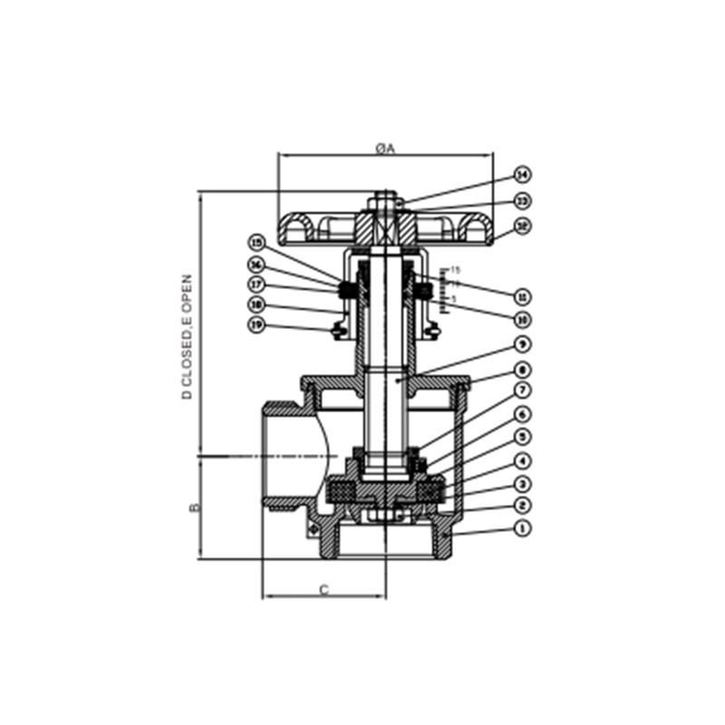
Pressure Reducing Angle Valve Main Parts:
- Angled Valve Body: Houses the entire assembly, with a 90-degree turn from inlet to outlet.
- Pressure Reducing Valve (PRV) Cartridge/Mechanism: The core component. A spring-loaded diaphragm or piston mechanism that automatically modulates to maintain a set outlet pressure.
- Inlet Connection (Female): Typically a female pipe thread (e.g., NPT) for connecting to the pressurized standpipe.
- Outlet Connection (Male): A male fire hose thread (NST/NH) for connecting the fire hose.
- Pressure Adjustment & Locking Mechanism: A screw or knob, often with a protective cap, to set the desired downstream pressure. It is lockable to prevent unauthorized tampering.
- Outlet Pressure Gauge Port: Connection point for a gauge to monitor the reduced outlet pressure.
- Test & Drain Valve: An integral or attached valve for flow testing and draining the device.
- Strainer/Screen: Often included at the inlet to protect the PRV mechanism from debris.
Role, Characteristics, and Application Scenarios of Pressure Reducing Device Angle Valve in Pipelines
Brass Valves Functions in Pipelines:
- Automatic Pressure Reduction: Maintains a constant, pre-set outlet pressure regardless of fluctuations in the main supply pressure.
- Over-Pressure Protection: Safeguards downstream hoses, nozzles, and equipment from damage due to excessive pressure.
- Firefighter Safety: Delivers a manageable, stable pressure and flow to the hose line, improving control and safety during firefighting operations.
- Flow Control & Isolation: Functions as a standard angle hose valve for turning water on/off to the hose.
Operational Features:
- Preset Outlet Pressure: Factory-set and field-adjustable within a specific range (e.g., 65-175 psi).
- Automatic Regulation: The internal mechanism constantly senses and adjusts to maintain the set pressure under varying flow conditions.
- Integral Bypass: Some models include a bypass for full main pressure if needed (e.g., for standpipe flow tests).
- Built-in Test/Drain: Allows for periodic functional testing and system drainage.
Pressure Reducing Device Angle Valve Standards: Materials, Design, and Connections
Fire Valves Material Standards:
- Body/Bonnet: ASTM B584 (Bronze) or ASTM A536 (Ductile Iron with corrosion-resistant coating).
- Internal Mechanism (Diaphragm, Piston, Springs): Stainless Steel, Brass, with Buna-N or EPDM diaphragms/seals.
- Strainer: Stainless Steel screen.
Design & Performance Standards:
- UL 1468 (US) / FM 1318 (US): Standard for Direct Acting Pressure Reducing Valves for Fire Protection Service.
- NFPA 14: Standard for the Installation of Standpipe and Hose Systems. Dictates performance and installation requirements (e.g., outlet pressure settings).
- ASSE 1049 (Performance for Plumbing): May be referenced for certain performance aspects.
- Hydrostatic Shell Test: Typically 2.5x to 3x the maximum inlet pressure rating.
Connection Standards:
- Inlet (Female - F): NPT (National Pipe Tapered) thread per ANSI/ASME B1.20.1. Common sizes: 1.5", 2.0", 2.5".
- Outlet (Male - M): NST (National Standard Thread) or NH (National Hose) fire hose thread per NFPA 1963. Common size: 1.5".
- Gauge Port: Typically 1/4" NPT male.
How to Select Pressure Reducing Device Angle Valve
Follow this purchasing guide:
Define Performance Specifications:
- Pressure Ratings: Specify maximum Inlet Pressure (e.g., 250 psi) and required Outlet Pressure Setting (e.g., 100 psi). Also, define the adjustable range.
- Flow Rate (K-factor): Required flow capacity in GPM or L/min, often defined by a K-factor.
- Size & Threads: Inlet pipe size (e.g., 2" NPT F) and outlet hose thread (e.g., 1.5" NST M).
- Material: Bronze is common for corrosion resistance. Specify coating for ductile iron.
Verify Mandatory Certifications:
- Non-negotiable: The device MUST be UL Listed (UL 1468) or FM Approved (FM 1318) for Fire Protection Service.
- Request the official listing/approval guide page or certificate.
Supplier Selection & Sourcing:
- Source from specialized fire protection system manufacturers or their authorized distributors (e.g., Reliable, Potter, Star).
- Provide detailed project specifications (e.g., from NFPA 14 hydraulic calculations) for vendor quotation.
- Request submittal data sheets, dimensional drawings, and installation manuals for engineering approval.
Pre-Shipment Inspection for Export Pressure Reducing Device Angle Valve and Key Considerations
Inspection Procedure:
Visual & Dimensional Check:
- Verify body integrity, coating quality, and clear, permanent markings (brand, model, size, pressure ratings, UL/FM mark).
- Ensure adjustment mechanism is intact and lockable. Cap should be present.
- Check all thread connections (inlet, outlet, gauge port) for damage using gauges.
Functional & Performance Test (Critical):
- Factory Test Certificate: Must be provided, showing successful shell test and performance/regulation test at various flow rates.
- Set Point Verification: If possible, spot-check that the outlet pressure setting is as ordered or falls within the specified range using a test bench.
- Operation: Handwheel/lever should operate the main valve smoothly. Adjustment mechanism should turn without binding.
Packaging & Documentation:
- Protection: All threaded connections must have heavy-duty plastic caps, securely fitted. The internal cavity should be clean and dry.
- Packaging: Use individual boxes with foam/cardboard inserts. Protect the pressure gauge port and adjustment knob from impact.
- Documents: Ensure Packing List, Factory Test Certificate, UL/FM Listing Documentation, and Installation/Operation Manuals are included.
Pressure Reducing Device Angle Valve Material List