


Flanged Y Strainer Model No. 6103 PN10/16
Flanged Y Strainer Model No. 6103 PN10/16 Definition and Components
A Flanged Y Strainer Model No. 6103 PN10/16 is a pipeline filtration device designed to the European pressure rating system. The model name decodes as follows:
- Flanged:Equipped with integral flanges for bolted connection.
- Y Strainer:The body is shaped like a "Y," with the straining element set in the branch.
- Model 6103:A manufacturer's designation, typically for a cast iron body Y strainer built to PN standards.
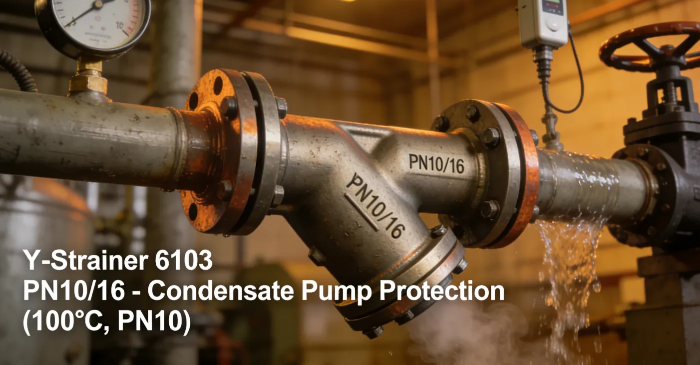
- PN10/16:Indicates a dual pressure rating. It is designed for a Maximum Allowable Working Pressure (MAWP) of 10 bar (~145 psi) at 120°C and 16 bar (~232 psi) at ambient temperature (usually 20°C). The usable pressure depends on the operating temperature of the system.
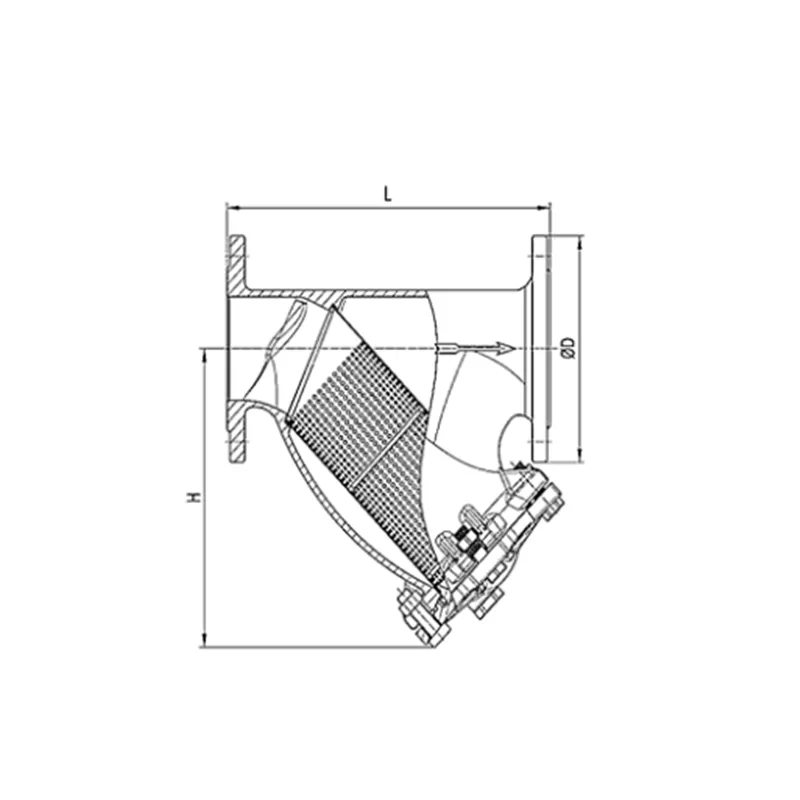
Main Parts:
- Body: Cast housing (typically gray cast iron EN-GJL-250) in a "Y" configuration with integrally cast PN10/16 flanges.
- Cover/Cap: Removable end (usually bolted) that seals the strainer chamber.
- Screen (Strainer Basket): A perforated or mesh cylinder (often stainless steel) that captures debris.
- Gasket: Seals the joint between the body and cover (e.g., EPDM, NBR).
- Blow-Off/Drain Plug: A plug or valve at the bottom of the screen chamber for draining debris.
- Bolts & Nuts: For assembling the cover and connecting to pipeline flanges.
Role, Characteristics, and Application Scenarios of Flanged Y Strainer Model No. 6103 PN10/16 in Pipelines
Y-Strainer Valve Functions:
- Particulate Filtration:Protects downstream equipment (pumps, control valves, heat exchangers) by trapping pipeline debris.
- System Protection:Prevents clogging and abrasive wear in sensitive components, ensuring system longevity and efficiency.
Y Strainer Valve Operational Features:
- Temperature-Dependent Pressure Rating:The key operational feature. The PN16 rating applies only at near-ambient temperatures (e.g., 20°C). For higher temperature services (e.g., hot water up to 120°C), the maximum allowable pressure drops to PN10. Always consult the manufacturer's pressure-temperature chart.
- Low Pressure Drop:The "Y" design minimizes flow restriction.
- Directional Flow:Must be installed with the screen leg pointing downward. An arrow on the body indicates flow direction.
- Service-Friendly:The bolted cover allows for easy screen access and cleaning.
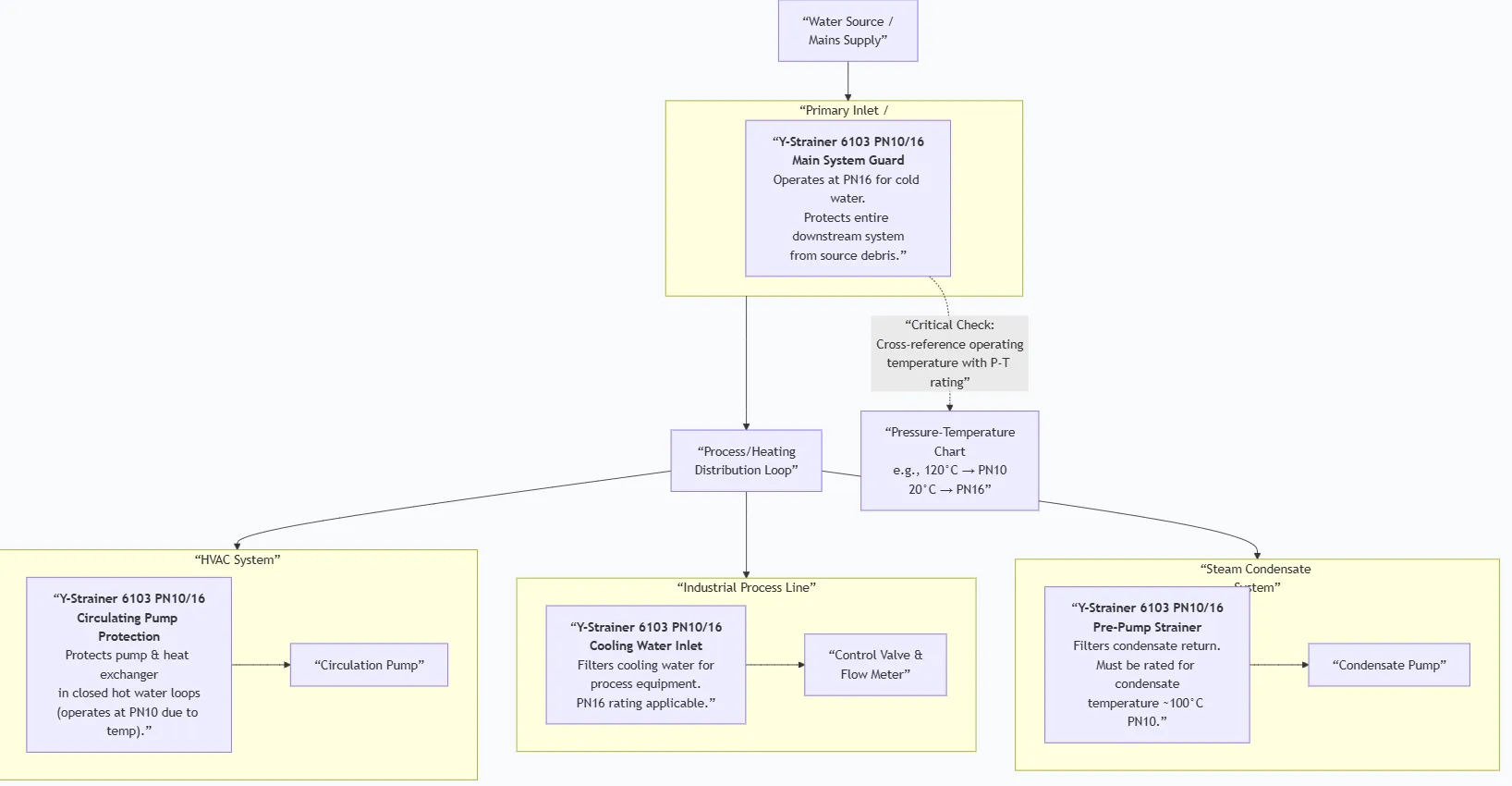
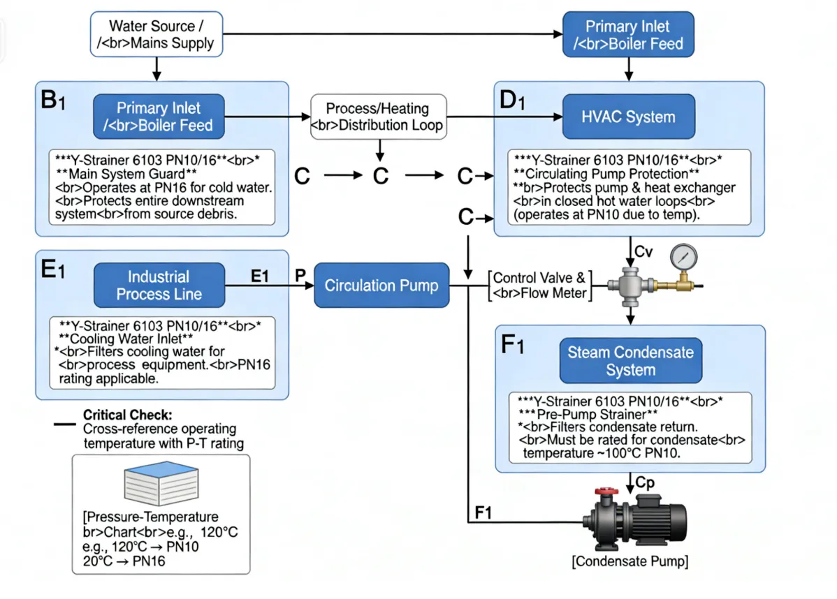
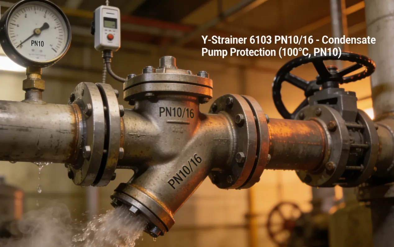
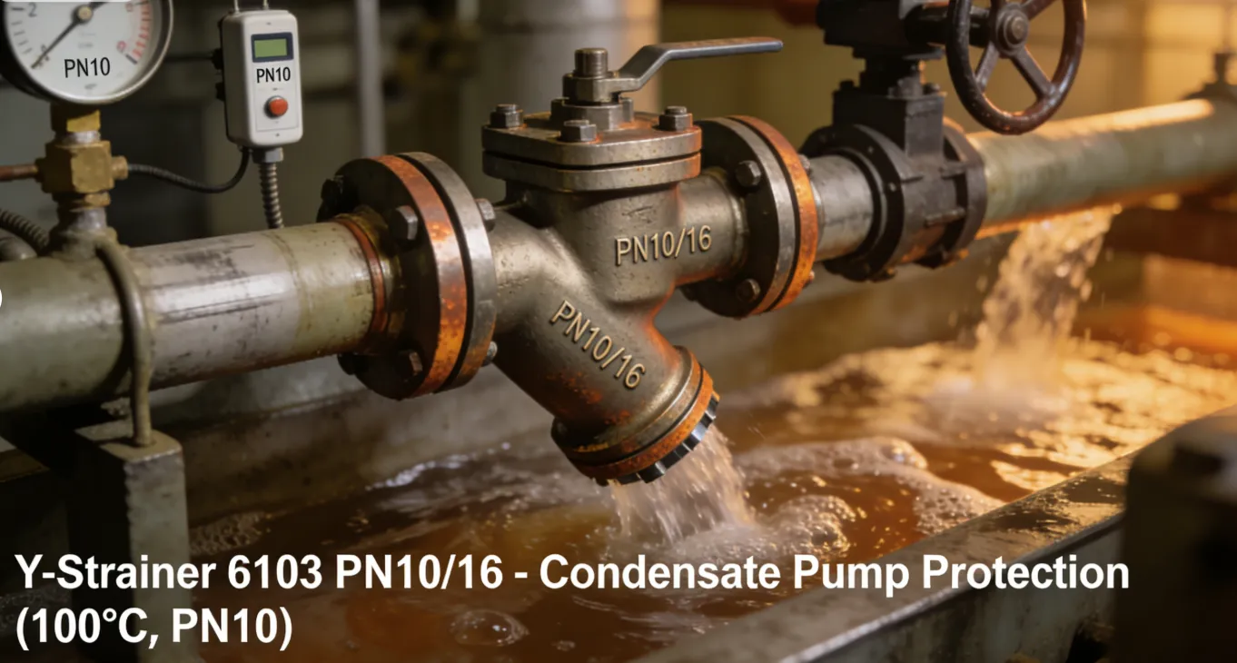
Primary Usage Scenarios:
Common in European and international projects for HVAC, industrial water circuits, general plant utilities, and low to medium-pressure steam lines where PN-flanged piping is used.
Scenario Diagram:
Flanged Y Strainer Model No. 6103 PN10/16 Standards: Materials, Design, and Connections
| Standard Type | Primary Standard(s) | Purpose & Key Specifications |
| Flange Design & Rating | EN 1092-2 | The definitive standard for PN-designated flanges. Specifies dimensions, sealing face types (Form B1, D, etc.), bolt holes, and materials for PN6, PN10, PN16, PN25, etc. |
| Pressure Equipment Design | EN 12516-1 / PED 2014/68/EU | EN 12516 specifies wall thickness for valve/strainer bodies. For CE marking, the design must comply with the Pressure Equipment Directive (PED). |
| Material Standards | EN 1561 EN-GJL-250 (Gray Cast Iron) - Common for body. | Specifies European material grades. EN-GJL-250 is typical for Model 6103. |
| EN 10213-4 GP240GH (Cast Carbon Steel) - Alternative. | ||
| EN 10088-2 (1.4301/1.4401) (Stainless Steel Screen) | ||
| EN 681-1 (Elastomer Gaskets) | ||
| Face-to-Face Dimensions | EN 558-1 | Standardizes face-to-face lengths for industrial valves with PN flanges. |
| Testing | EN 12266-1 | Standard for pressure testing of valves, including shell strength tests. |
How to Select Flanged Y Strainer Model No. 6103 PN10/16
Step 1: Define Precise Specifications
Clarity on pressure-temperature service is crucial for PN-rated equipment.
- Service Conditions:Must specify both Fluid and Maximum Operating Temperature. This determines whether PN10 or PN16 applies.
- Size & Flange Spec:Nominal Diameter (e.g., DN150) and full flange detail: "EN 1092-2 PN10/16, Form B1 (Raised Face), Drilling Series ..."
- Screen Specification:Define screen perforation size or mesh (e.g., "2.0 mm perforations").
- Materials:Body material (e.g., EN-GJL-250), Screen material (e.g., AISI 304 / 1.4301), Gasket material.
- Certification:Specify if CE Marking under PED is required (likely for pressure equipment in Europe).
Step 2: Source from Suppliers Familiar with EN Standards
- Source from European manufacturers or distributors specializing in PN-rated valves and fittings.
- Request the official Pressure-Temperature Rating Chartfor the model.
- For CE-marked products, request the Declaration of Conformity (DoC)and relevant module certificates (e.g., Module H1).
Step 3: Order Execution
- Confirm lead times.
- Required documents: Commercial Invoice, Packing List, Certificate of Conformity (CoC) with P-T rating, Material Certificates per EN 10204 Type 3.1, and if applicable, CE DoC.
Pre-Shipment Inspection for Export Flanged Y Strainer Model No. 6103 PN10/16 and Key Considerations
Fire Fighting Valves Types Inspection Checklist:
| Category | Check Point | Acceptance Criteria |
| Documentation | 1. Pressure-Temperature Chart | Must be provided and clearly show PN10/16 ratings. |
| 2. Material Certificates | EN 10204 Type 3.1 certificates for the cast iron body. | |
| 3. CE Marking Docs (if applicable) | Declaration of Conformity must be included. | |
| 4. Test Certificate | Shell test certificate per EN 12266-1. | |
| Physical/Functional | 5. Marking | Body must be clearly marked with PN10/16, material designation (e.g., EN-GJL-250), size (DN), and manufacturer. |
| 6. Flange Inspection | Verify flange dimensions (OD, thickness, bolt circle) against EN 1092-2 for PN16. Faces must be smooth. | |
| 7. Screen Integrity | Screen must be clean, undamaged, and of the specified perforation size. | |
| 8. Gasket & Sealing Surfaces | Gasket must be new and undamaged. Body and cover sealing surfaces must be clean and even. | |
| Packaging | 9. Flange Face Protection | Rigid plastic or wooden protectors must be bolted to the flange faces. |
| 10. Internal Cleanliness & Dryness | Body interior and screen must be completely clean, dry, and free of oil/grease (especially for oxygen service or food applications). |
Key Precautions for Export:
- Pressure Rating Visibility:Ensure the "PN10/16" marking is clearly visible and not painted over. This is critical for the end-user's safety and compliance.
- Anti-Corrosion for Cast Iron:Cast iron is prone to rust. Apply a suitable, non-sticky VCI (Vapor Corrosion Inhibitor) spray or gel to all machined surfaces (flange faces, bolt holes) before applying the protectors.
- Secure Internal Components:If the screen is installed, ensure it is centered and the strainer is packed in its normal operating orientation (screen leg down) to prevent the screen from shifting and deforming.
- Separate Kit for Assembly:Pack all assembly bolts, gaskets, and the drain plug in a sealed, labeled bag securely fastened inside the crate.
- Documentation in the Crate:Place the P-T rating chart, material certificates, and test report in a waterproof pouch inside the shipping crate. This ensures they reach the installation technician, not just the purchasing office.
Flanged Y Strainer Model No. 6103 PN10/16 Size Chart