


Balancing Valve SP45F
Balancing Valve Purpose
Digital lock balance valve is a multi-functional liquid flow control valve, t can be convenient and accurate regulation of flow, widely used in heating and air conditioning system and other need to regulate the flow of pipeline system.
Balancing Valve Definition and Components
What is a Balancing Valve SP45F and its Main Parts?
The Balancing Valve SP45F is a manual, calibrated regulating and measuring valve. It is a subtype of globe or angled pattern valve designed not just to throttle flow, but to precisely measure the pressure drop across itself, allowing for the accurate calculation and adjustment of flow rates in a hydraulic circuit. "SP45F" is a common series designation from manufacturers like Tour & Andersson (TA), IMI Hydronic, or similar.
Water Valves Main Components:
Valve Body: Typically a globe or angle pattern with flanged or threaded connections. Contains a shaped plug and seat designed for stable flow characteristics
Calibrated Adjustment Stem & Handwheel: A fine-threaded stem attached to the plug. The handwheel often has a calibrated scale or can be locked in position. Each turn corresponds to a precise change in valve opening (Kvs value).
Two Pressure Test Ports (Tappings): The defining feature. Two specially designed ports (upstream and downstream of the plug) allow for the connection of a differential pressure gauge or a handheld electronic flow meter.
Diaphragm Seal or Piston: Many advanced models include an internal diaphragm to separate the system fluid from the stem seal, ensuring precise, friction-free adjustment and no leakage.
Memory Stop: A feature that allows the valve to be closed for service and then re-opened to the exact pre-set position.
Locking Mechanism: A provision to lock the setting with a sealing cap or device to prevent unauthorized tampering.
Plug & Seat: Engineered to provide a linear or equal percentage flow characteristic, enabling predictable regulation.
Role, Characteristics, and Application Scenarios of Balancing Valve in Pipelines
water balancing valve Functions, Operational Features, and Usage Scenarios
Functions in Hydraulic Systems:
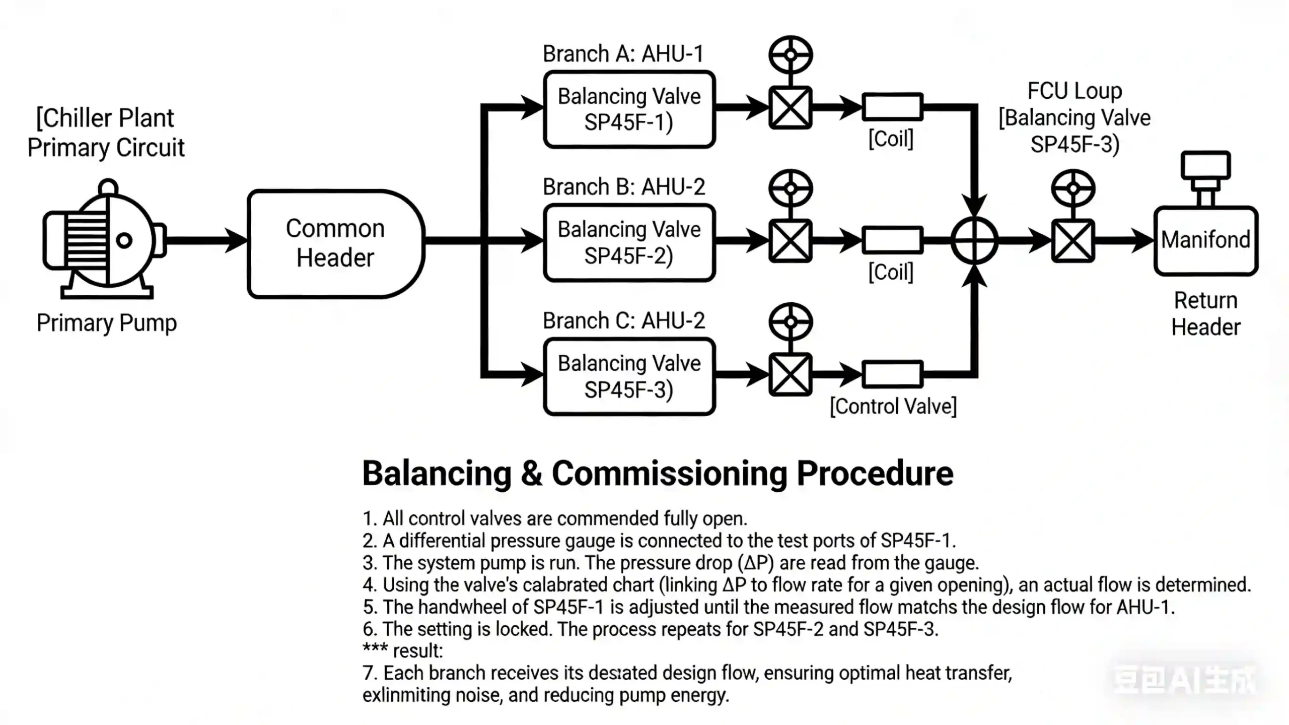
Hydronic Balancing: To proportionally distribute the correct design flow of water (hot or chilled) to each terminal unit (coil, radiator, fan coil) in a system.
Flow Measurement & Commissioning: Used with a differential pressure gauge and the valve's pre-calibrated chart (or a flow meter) to measure actual flow rate without intrusive measurement.
Regulation & Throttling: To create a designed pressure drop, stabilize system hydraulics, and eliminate overflows/short-circuiting.
Isolation: Can serve as a shut-off valve for maintenance of the branch it serves.
Operational Features:
Measuring Function: The integrated test ports enable accurate, in-situ flow measurement, which is its core advantage over a standard manual valve.
Predictable Flow Characteristics: Has a documented Kvs value (flow coefficient at full open) and a known flow curve (linear or equal percentage), allowing for precise setting.
Low Leakage & High Repeatability: Designed to maintain its setting over time and provide tight shut-off when required.
Presettable: Can be pre-set in the workshop based on design calculations before installation
Typical Usage Scenarios
HVAC Systems: In the return or supply lines of chillers, cooling towers, air handling units (AHUs), fan coil units (FCUs), and radiator circuits
District Heating/Cooling Networks: At building entry points (substations) and within building distribution risers.
Industrial Process Cooling: To balance flow to multiple heat exchangers or cooling jackets.
Solar Thermal Systems: To balance flow across multiple collector arrays.
Balancing Valve Standards: Materials, Design, and Connections
Material, Design, and Connection Standards
Material Standards:
Valve Body: Cast Iron (EN-GJL-250), Ductile Iron (EN-GJS-400-18), Bronze (CW617N), or Cast Steel (WCB). For HVAC, cast iron is common.
Internal Parts: Stem & Plug - Stainless Steel (AISI 304/316). Seat - Stainless Steel or EPDM-coated for tight shut-off.
Seals & Diaphragm: EPDM (standard water), NBR, or Viton for high temps/oils.
Test Port Plugs: Brass or Stainless Steel.
Design & Performance Standards:
Pressure-Temperature Rating: EN 12266, ASME B16.34.
Flow Coefficient & Testing: ISO 10633 (Industrial valves) or more specifically, EN 215 (Thermostatic radiator valves) for characteristics. The Kvs testing follows ISO 5208.
Face-to-Face Dimensions: EN 558-1, ISO 5752, or ASME B16.10.
Leakage Class: Seat leakage typically Class IV or better per EN 12266
Connection Standards:
Flanged: EN 1092-2 (PN16/PN25), ASME B16.1 (Class 125/250), or ASME B16.5 (Class 150).
Threaded: Female threads (BSPP - ISO 228, or NPT - ASME B1.20.1).
Grooved: For specific installations per ISO 4144 or AWWA C606.
Test Ports: Standard G ½" or ¼" female thread for connecting hoses
How to Select Balancing Valve
Procurement Process
Define Application Parameters:
Fluid & Temperature: Water, glycol mix, temperature range.
Pressures: Design working pressure (PN16/PN25/Class 150)
Flow Data (Critical): Design Flow Rate (Q) for each valve location and the Required Pressure Drop (ΔP) at that flow. This is used for sizing (selecting the correct Kvs).
Sizing Rule: Select a valve where the design flow falls between 50-100% of the valve's capacity at full open to ensure good regulation.
Characteristic: Choose linear (for constant ΔP systems) or equal percentage (for variable ΔP systems, like those with variable speed pumps).
Supplier Selection:
Specialized hydronic balancing valve manufacturers (e.g., IMI Hydronic, TA, Griswold, Venturi) are preferred.
Request sizing software from the vendor to confirm selection.
Technical Review
Review submitted datasheets, Kvs charts, and flow curves.
Confirm the presence of test ports, memory stop, and locking mechanism.
Ensure the materials are suitable for the system fluid (e.g., inhibitor-friendly seals).
Commercial & Logistics:
Lead times are moderate (6-12 weeks).
Order a Field Measurement Instrument (differential pressure gauge with hoses) or a dedicated balancing meter simultaneously
Spare Parts: Request O-ring/seal kits for the test ports and stem seal.
Support Requirements:
Demand the official, calibrated flow charts for each valve size/Kvs purchased.
Require installation and balancing procedure manuals.
Pre-Shipment Inspection for Export Balancing Valve and Key Considerations
Pre-Shipment Inspection & Export Precautions
Inspection & Testing Checklist:
Documentation Review: Verify material certificates, flow characteristic charts (Kvs documentation), and assembly drawings.
Visual & Dimensional: Check for damage, proper marking (PN, Kvs, flow direction arrow), and that test port plugs are present and tight. Verify flange drilling or thread dimensions.
Functional Tests (Sample basis or 100% depending on order):
Shell & Seat Leakage Test: Per EN 12266. The valve body is pressure tested, and the seat is tested for leakage in the closed position.
Stem Operation Test: Ensure the handwheel turns smoothly throughout the entire travel, with no binding.
Test Port Function Check: Verify that the test ports are clear and that the seals under the port plugs are intact.
Key Precautions for Export:
Internal Protection: The valve interior must be clean and dry. Apply a light, compatible anti-corrosion spray if necessary.
Critical Component Protection: The calibrated stem and test ports are delicate. The test ports must be securely plugged with metal plugs. The handwheel/stem should be locked in a mid-position using cardboard or foam to prevent rotation during transit.
Flange Face Protection: Use heavy-duty plywood or plastic covers bolted to the flanges. Do not use tape alone.
Packing: Wrap each valve individually in VCI (Vapor Corrosion Inhibitor) paper. Pack in a sturdy cardboard box or wooden crate with ample packing material to prevent movement. Include desiccant bags.
Documentation: Place a waterproof pouch containing the valve's specific flow chart, inspection certificate, and packing list inside the box. Mark the exterior clearly with "PRECISION INSTRUMENT," "KEEP DRY," and the valve's unique ID.
By following this process, you ensure the procurement of a vital commissioning tool that guarantees the hydraulic efficiency, comfort, and energy performance of the fluid system
Balancing Valve Main part material
| Part | Material |
| Body | Cast iron/Ductile iron |
| Bonnet | Cast iron/Ductile iron |
| Disc | Stainless steel |
| Seat | PTFE |
| Stem | 2Cr13 |
| Gasket | XB450 |
| Hand wheel | Q235 |
| Test valve | Cooper |
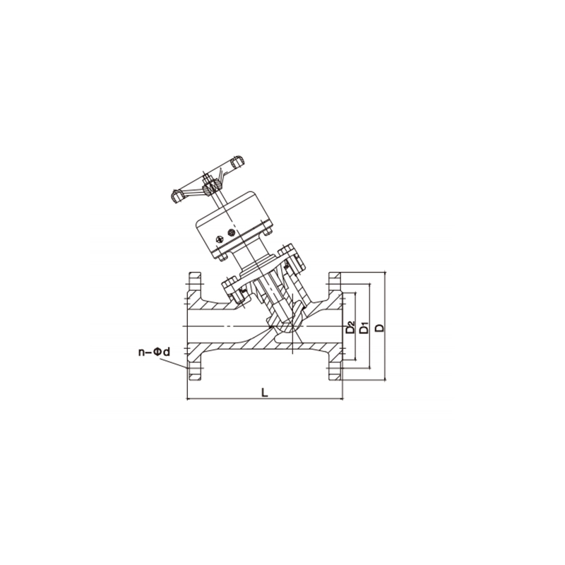
Balancing Valve Main dimensions(mm)
| DN | 50 | 65 | 80 | 100 | 125 | 150 | 200 | 250 | 300 | |
| L | 232 | 258 | 284 | 310 | 335 | 364 | 470 | 560 | 600 | |
| D | PN10 | 160 | 180 | 190 | 215 | 245 | 280 | 335 | 405 | 455 |
| PN16 | 160 | 180 | 190 | 215 | 245 | 280 | 335 | 405 | 455 | |
| D1 | PN10 | 125 | 145 | 160 | 180 | 210 | 240 | 295 | 350 | 400 |
| PN16 | 125 | 145 | 160 | 180 | 210 | 240 | 295 | 355 | 410 | |
| n-Фd | PN10 | 4-18 | 4-18 | 8-18 | 8-18 | 8-18 | 8-23 | 8-23 | 12-23 | 12-23 |
| PN16 | 4-18 | 4-18 | 8-18 | 8-18 | 8-18 | 8-23 | 12-23 | 12-26 | 16-26 | |
Note:1. Other specifications and flange standards are available upon request.
- Design and specifications are subject to change without prior notice.