.png)
.png)


Dry Alarm Check Valve
Dry Alarm Check Valve Definition and Components
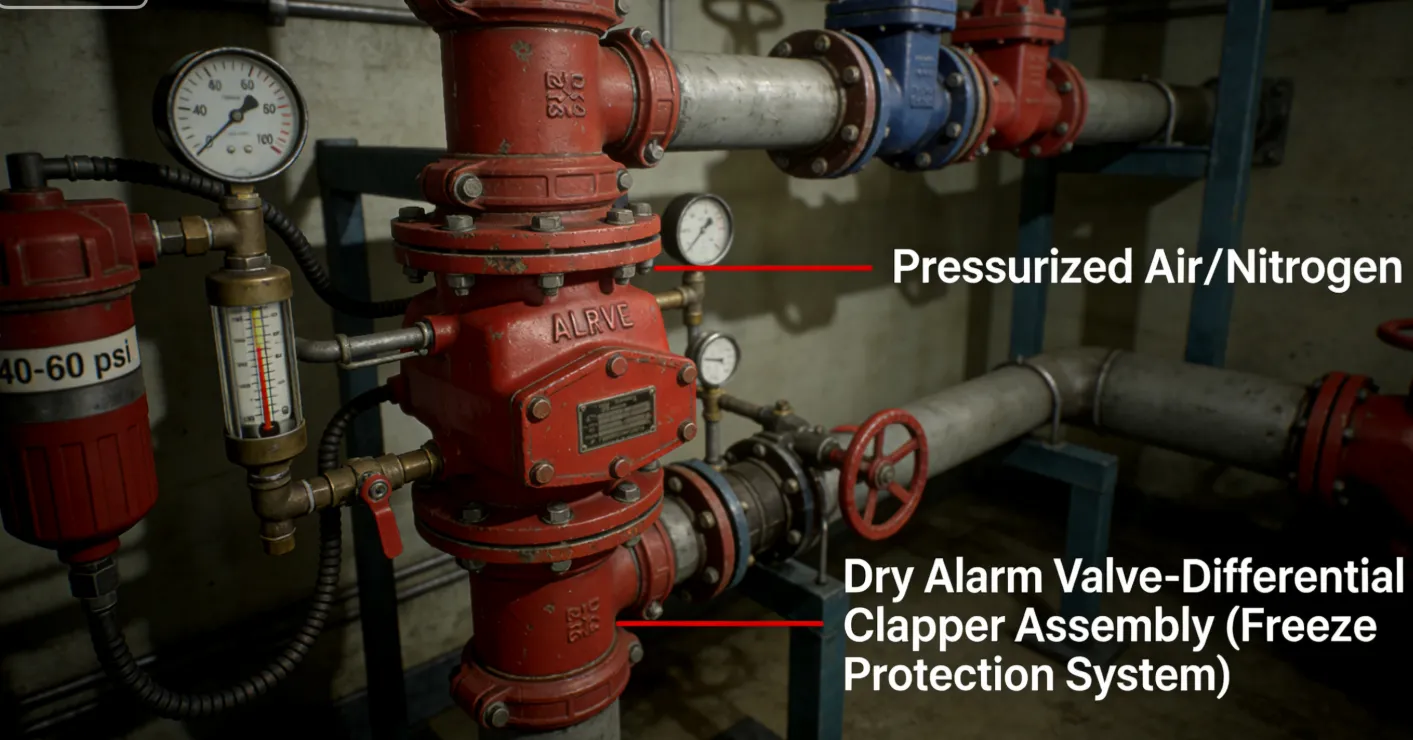
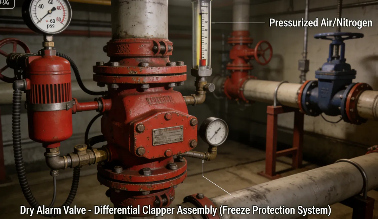
A Dry Alarm Check Valve is the central control assembly for a dry-pipe fire sprinkler system. It is a specialized, differential-type valve that keeps water out of the system piping (which is filled with compressed air or nitrogen) until a sprinkler activates. Upon activation, it releases the air, allows water to enter, and triggers an alarm.
Key Terminology:
- Dry:For use in "dry-pipe" systems where the piping is filled with compressed air or nitrogen to prevent freezing.
- Differential Design:The valve clapper is designed with a larger surface area on the air (system) side than the water (supply) side. A small amount of "priming water" creates a seal, and the higher air pressure holds the clapper tightly closed against the incoming water pressure.
- Alarm:Incorporates ports that activate alarms when air pressure drops and water begins to flow.
Main Parts:
- Main Valve Body: Houses the differential clapper assembly.
- Differential Clapper & Seat: The core mechanism. A rubber-faced clapper with a larger diameter on the top (system side) than the bottom (supply side).
- Priming Water Reservoir: The space above the clapper is filled with a small amount of water to create an airtight seal.
- Air Pressure Gauge: Monitors the supervisory air pressure in the system piping (typically 20-40 psi).
- Water Pressure Gauge: Monitors the incoming water supply pressure.
- Intermediate Chamber (Alarm Port): A chamber between the clapper seat and the alarm line. When the clapper opens, water rushes into this chamber.
- Trim (Piping) Assembly: Includes the priming water level check valve, alarm line valve, drain valves, and connections for the air supply (exhauster/maintenance device).
- External Reset Mechanism: A handwheel or lever to manually reset the clapper after operation.
Role, Characteristics, and Application Scenarios of Dry Alarm Check Valve in Pipelines
Functions:
- System Sealing: Maintains a reliable air/water seal to prevent water from entering the dry piping.
- Quick Opening: Rapidly opens when air pressure drops to minimize water delivery time.
- Alarm Activation: Triggers hydraulic (water motor gong) and electrical (pressure switch) alarms upon water flow.
- System Reset: Allows the system to be drained, reset, and re-pressurized with air after operation.
Operational Features:
- Differential Principle: A small, constant air pressure (e.g., 20 psi) can hold back a much higher water pressure (e.g., 100 psi) due to the clapper's area differential.
- "Water Delivery Time" is Critical: Dry systems have a maximum allowable time for water to reach the most remote sprinkler (per NFPA 13). Valve design and system size are optimized for this.
- Priming Water Seal: Requires maintenance to ensure the proper water level is maintained to prevent air leakage past the clapper.
- More Complex than Wet Valves: Requires an air maintenance compressor or nitrogen supply and more involved testing.
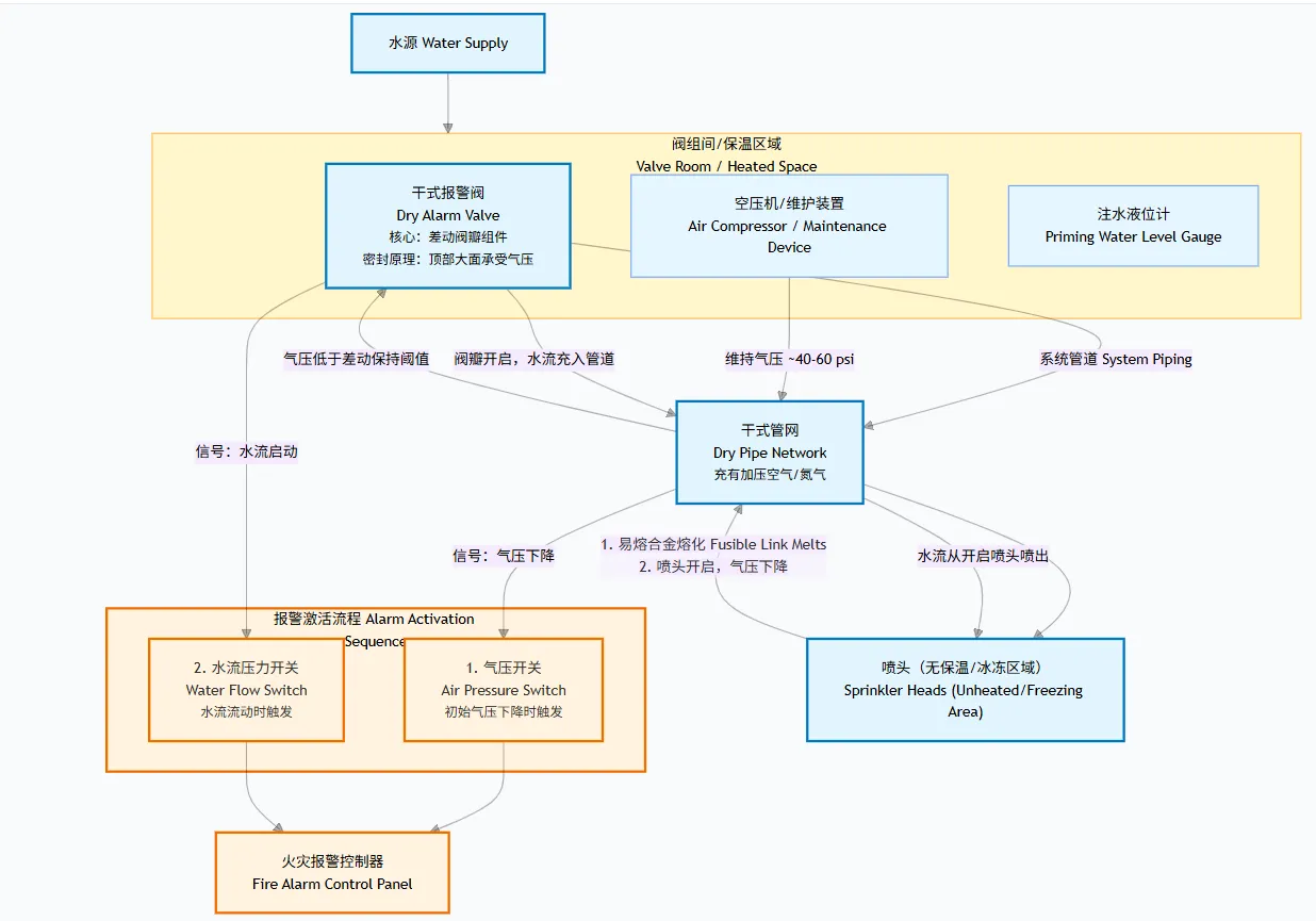
Fire Sprinkler Alarm Check Valve Primary Usage Scenarios:
Used as the main control valve for dry-pipe fire sprinkler systems in unheated areas where water in the pipes would freeze (e.g., parking garages, warehouses, attics, freezers, loading docks).
Scenario Diagram:


Dry Alarm Check Valve Standards: Materials, Design, and Connections
| Standard Type | Primary Standard(s) | Purpose & Key Specifications |
| Design & Performance | UL 260 / FM 1110 | The essential listing standards for Dry Pipe Alarm Valves in North America. These standards validate the valve's operational timing and reliability. |
| Fire System Code | NFPA 13 | Dictates the installation requirements, including maximum water delivery time, air pressure settings, and valve sizing for dry systems. |
| Material Standards | ASTM A126 Class B (Gray Iron Body). | Materials must withstand corrosive priming water and varying temperatures. |
| ASTM A536 (Ductile Iron) for higher durability. | ||
| ASTM B584 (Bronze) for trim valves. | ||
| Stainless Steel for clapper shaft and springs. | ||
| Connection Standards | ASME B16.1 Class 125/250 (Flanged) - Standard. | Flanged connections prevail. Sizes commonly range from 2" to 8" based on system hydraulic calculations. |
| AWWA C110 (Ductile Iron Flanges). | ||
| Air Supply | NFPA 13 | Governs the requirements for the air/nitrogen maintenance equipment (compressors, air dryers, regulators). |
How to Select Dry Alarm Check Valve
Step 1: Define Specifications from System Design
The valve is specified by the fire protection engineer based on complex calculations.
- Size & Orifice:Determined by hydraulic calculations to meet water delivery time Specify the orifice size (e.g., 1", 1-1/4") which is critical for dry valve performance.
- Listing Requirement:Must specify: "UL 260 Listed and/or FM Approved Dry Pipe Alarm Valve."
- Pressure Ratings:Specify both maximum water working pressure and maximum air working pressure.
- Trim & Accessories:Specify required trim (priming check valve, alarm line valve, drains) and required gauges. The Air Maintenance Device (compressor, air dryer, low-pressure switch) is typically a separate but coordinated purchase.
- Connection Type:Flanged, per riser diagram (e.g., ASME B16.1 Class 125).
Step 2: Source from Fire Protection Specialists
- Purchase only from authorized distributors of major fire protection manufacturers (e.g., Victaulic/Viking, Tyco, Reliable).
- Require a complete submittal package, including: UL/FM listing sheets, detailed dimensional drawings, water delivery time charts, and a schematic of the recommended trim.
- The engineer must review and approvethe submittal, ensuring the selected valve meets the calculated system demand.
Step 3: Order Execution
- The purchase order must reference the approved submittals.
- Consider lead times, as dry valves are less common than wet valves and may not be standard stock.
Pre-Shipment Inspection for Export Dry Alarm Check Valve and Key Considerations
Inspection Checklist:
| Category | Check Point | Acceptance Criteria |
| Documentation | 1. UL/FM Listing Mark | Permanently affixed to the valve body. |
| 2. Listing Documentation | Official guide card or report for the specific model and orifice size. | |
| 3. Hydrostatic & Air Test Certificates | Proof of shell/seat pressure tests and functional air hold test. | |
| Physical/Functional | 4. Clapper & Seat Condition | Inspect the differential clapper face and seat for imperfections. The sealing surface must be flawless. |
| 5. Priming Water Check Valve | This small valve must operate freely to maintain the proper water level. | |
| 6. Internal Cleanliness & Dryness | CRITICAL: The valve interior and all internal passages must be completely dry to prevent freezing damage during transit. | |
| 7. Gauges & Trim Valves | All should be closed and protected. Gauges are best removed and packed separately. | |
| Packaging | 8. Clapper Securement | The clapper must be mechanically blocked or strapped in the closed position to prevent damage during shipping. |
| 9. Moisture Prevention | Desiccant (Silica Gel) bags must be placed inside the valve body and all pipe openings. Openings should be sealed with waterproof tape and caps. |
Fire Valves Key Precautions for Export:
- Extreme Dryness is Non-Negotiable:After final testing, the valve must be thoroughly blown dry with compressed air and immediately sealed. Residual moisture will freeze and cause costly damage.
- VCI Protection:Use Vapor Corrosion Inhibitor (VCI) powder or spray inside the valve body to protect ferrous components from rust during ocean transit.
- Protect the Clapper Seat:The precision-machined seat is easily damaged. The shipping block must prevent any impact or vibration from causing the clapper to chatter against the seat.
- Separate Crate for Accessories:Pack sensitive accessories like the Air Maintenance Device, pressure switches, and gauges in their own, cushioned boxes. Do not leave them installed.
- Clear Documentation:Include a waterproof pouch inside the main crate containing the installation manual, test reports, listing card, and a specific warning about ensuring the valve is dry before storage or installation.
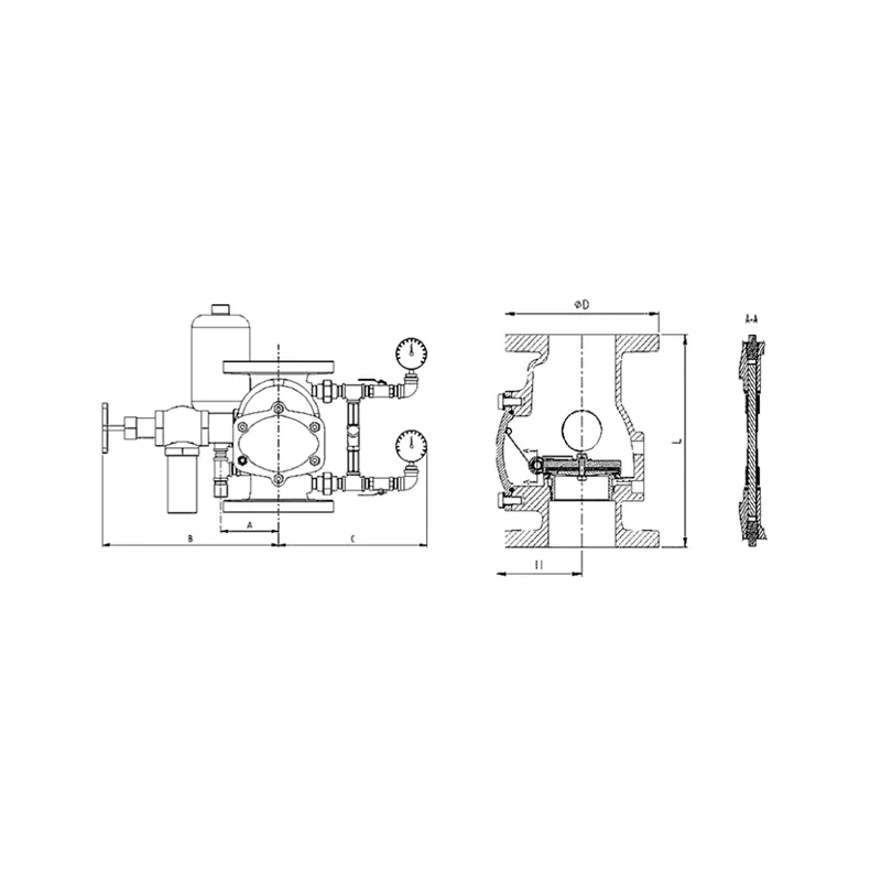
Dry Alarm Check Valve Size Chart
| Dimensions | Pressure rating | Size(mm) | |||||||
| DN | inch | psi | Φ D
|
L | H | A | B | C | E |
| 80 | 3 | 300 | 190 | 283 | 120 | 120 | 296 | 300 | 238 |
| 100 | 4 | 300 | 229 | 305 | 127.5 | 120 | 365 | 305 | 182 |
| 150 | 6 | 300 | 280 | 394 | 182 | 120 | 402 | 330 | 218 |
| 200 | 8 | 300 | 345 | 457 | 214 | 120 | 424 | 365 | 248 |