


Flanged Resilient Seated NRS Gate Valve with Indicator Post
Flanged Resilient Seated NRS Gate Valve with Indicator Post Definition and Components
A standard resilient seated nrs gate valve with post indicator extension that shows valve position (open/closed) from ground level when buried. Model Z45X-04: Z=gate valve, 45=flanged, X=resilient seat, 04=with indicator post version.
Main Parts:
- Standard Valve Components: Body, gate, stem, bonnet, flanges
- Indicator Post Extension: Steel pipe extension (typically 2-6 ft)
- Position Indicator: Visual display at top showing open/closed
- Tee Handle or Operating Nut: For operation from ground level
- Protective Cover: Weatherproof cap for indicator post
- Buried Service Package: Extended stem, protected components
Role, Characteristics, and Application Scenarios of Flanged Resilient Seated NRS Gate Valve with Indicator Post in Pipelines
Functions:
- Underground pipeline isolation with above-ground operation
- Valve position indication without excavation
- Corrosion protection for buried installations
- Easy access for maintenance and operation
Fire valves Operational Features:
- Ground-level operation - no digging required
- Visual position indicator - clear open/closed status
- Extended stem - connects buried valve to surface
- Weatherproof design - suitable for outdoor burial
- Lockable cap - for security and tamper prevention
Fire gate valve Typical Applications:
- Buried water distribution lines
- Underground fire protection systems
- Subsurface irrigation control
- Municipal utility vaults
- Industrial buried piping
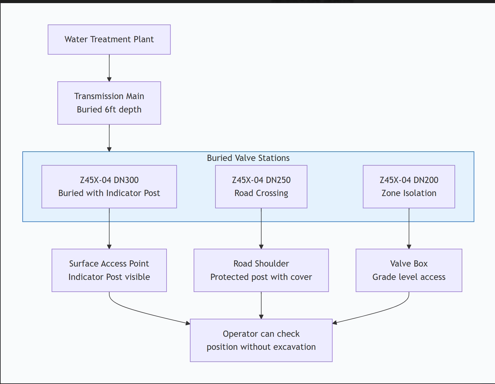
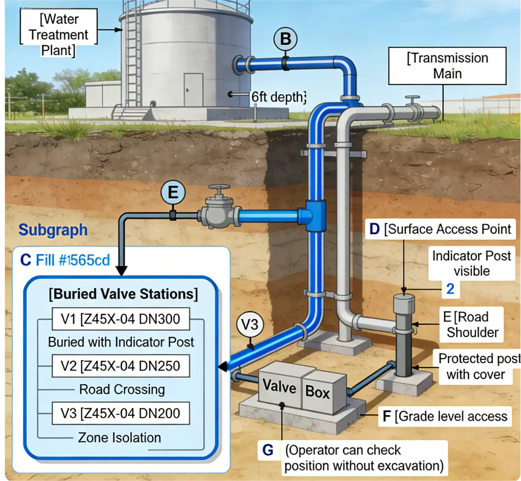
Scenario Diagram:
Flanged Resilient Seated NRS Gate Valve with Indicator Post Standards: Materials, Design, and Connections
Material Standards:
- Body/Bonnet: Ductile iron ASTM A536
- Stem (Extended): Stainless steel AISI 304/316
- Indicator Post: Galvanized steel pipe ASTM A53
- Protective Coating: Fusion-bonded epoxy or hot-dip galvanized
- Indicator Mechanism: Brass/stainless steel components
Design Standards:
- Valve: AWWA C509 or ISO 5208
- Buried Service: AWWA C550 for coatings
- Indicator Post: Manufacturer standard (typically 2" or 3" pipe)
- Extension Length: Customizable (typically 2-6 feet)
- Operating Torque: Designed for extended stem operation
Connection Standards:
- Flanges: ANSI B16.1 Class 125/250 or EN 1092-2 PN10/16
- Post Connection: Threaded or bolted to valve bonnet
- Surface Fitting: Standard tee handle or nut driver
- Protective Cover: Lockable, weather-resistant design
Additional Standards:
- Corrosion Protection: ISO 12944 for buried applications
- Potable Water: NSF/61 compliant materials
- Load Rating: Traffic-rated covers for road applications
How to Select Flanged Resilient Seated NRS Gate Valve with Indicator Post
Key Steps:
- Specify Requirements:
- Valve size and pressure rating
- Indicator post length (critical dimension)
- Burial depth requirements
- Surface fitting type (tee handle, nut, wheel)
- Locking mechanism requirements
Special Considerations:
- Extension length from valve centerline to grade
- Traffic loading if under roadways
- Corrosion protection level for soil conditions
- Position indicator type (visual, lockable)
Supplier Requirements:
- Experience with buried valve packages
- Custom fabrication capability for extensions
- Corrosion protection expertise
- AWWA/ISO compliance
Documentation Needed:
- Custom drawing approval (showing post length)
- Coating specifications for buried service
- Installation instructions for buried valves
Critical Specifications:
- Post length: ______ (from valve center to grade)
- Surface fitting: Tee handle / Operating nut / Wheel
- Lock type: Standard / High security
- Cover: Flush mount / Raised / Traffic-rated
- Coating: Epoxy / Galvanized / Dual protection
Pre-Shipment Inspection for Export Flanged Resilient Seated NRS Gate Valve with Indicator Post and Key Considerations
Inspection Focus Areas:
- Indicator Post Assembly:
- Verify extension length matches specifications
- Check post vertical alignment
- Test indicator mechanism (smooth operation)
- Verify position accuracy (open/closed indication)
Buried Service Components:
- Coating thickness and coverage
- Weld quality on extensions
- Thread protection on exposed threads
- Weatherproofing of indicator mechanism
Special Tests:
- Extended stem operation test - torque measurement
- Indicator accuracy test - position verification
- Weatherproof test - seal integrity of cover
- Load test - for traffic-rated covers
Export Precautions:
- Long components: Special crate design for post extensions
- Delicate indicators: Extra padding for visual indicators
- Multiple pieces: Clearly mark all components for assembly
- Installation guide: Detailed instructions for buried installation
Documentation Package:
Assembly drawings with dimensions
Coating certificates for buried service
Torque specifications for extended operation
Burial installation instructions
Maintenance manual for indicator mechanism
Field Verification Requirements:
Before shipment, verify:
Post length matches burial depth requirements
Indicator shows correct valve position
Surface fitting compatible with local tools
All components suitable for soil conditions at destination
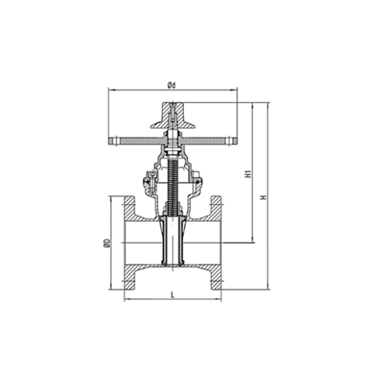
Flanged Resilient Seated NRS Gate Valve with Indicator Post Size Chart