.png)
.png)


Flanged Y Strainer No. 6101 ASME-B16.1 Class125
Flanged Y Strainer Definition and Components
A Flanged Y Strainer Model No. 6101 ASME-B16.1 Class125 is a pipeline fitting designed to mechanically remove solid debris (scale, rust, sediment) from flowing liquids or gases to protect downstream equipment. Its name describes its key features:
- Flanged:Has integral flanges for bolted connection to the pipeline.
- Y Strainer:The body is shaped like a "Y," with the strainer screen set at an angle in the branch, allowing for continuous flow during servicing.
- Model 6101:A common manufacturer's designation for a standard cast iron Y strainer.
- ASME-B16.1 Class125:Specifies that the flanges conform to the ASME B16.1 standard for Cast Iron Pipe Flanges and Flanged Fittings, with a pressure-temperature rating of Class 125.
Y Strainer Valves Main Parts:
- Body: Cast housing in a "Y" shape, typically cast iron for this model.
- Cover/Cap: Removable end (usually threaded or bolted) that provides access to the screen.
- Screen (Strainer Basket/Element): Perforated metal cylinder or mesh that captures debris. The hole size (mesh) is critical.
- Gasket: Seals the joint between the body and the cover.
- Blow-Off Valve/Drain Plug: A small valve or plug at the bottom of the screen chamber to allow for draining and flushing of collected debris without removing the cover.
Role, Characteristics, and Application Scenarios of Flanged Y Strainer in Pipelines
Y Strainer Valve Functions:
- Filtration/Protection:Primary function is to catch and hold pipeline debris.
- Equipment Safeguard:Protects sensitive and expensive downstream equipment such as pumps, meters, control valves, solenoid valves, and heat exchangers from damage, clogging, or reduced efficiency.
- System Integrity:Helps maintain clean process fluid and prevents particulate-related blockages.
Fire Fighting Valves Types Operational Features:
- In-line Filtration:Screens particles larger than the screen's perforations while allowing flow to continue.
- Low Pressure Drop:The angled "Y" design and careful screen selection aim to minimize flow restriction.
- Easily Cleanable:The cover can be removed to access and clean the screen. Flow does not need to be fully interrupted if valves are installed around the strainer.
- Direction-Sensitive:Must be installed with the screen leg pointing downward so debris collects in the pocket and doesn't re-enter the flow. An arrow on the body indicates flow direction.
- Requires Maintenance:Performance degrades as the screen clogs, increasing pressure drop. Must be monitored and cleaned periodically.
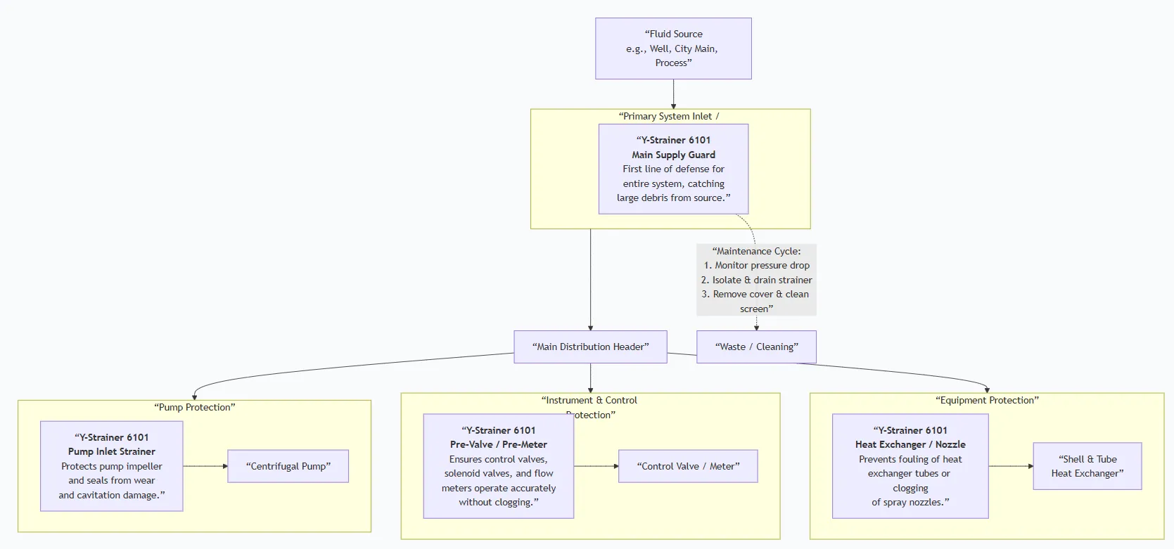
Primary Usage Scenarios:
Installed upstream of any critical equipment in liquid or gas systems where particulate contamination is a concern. It is a fundamental component of a well-designed piping system.
Scenario Diagram:
Flanged Y Strainer Standards: Materials, Design, and Connections
| Standard Type | Primary Standard(s) | Purpose & Key Specifications |
| Flange Design & Rating | ASME B16.1 | The key standard in the model name. Governs dimensions, tolerances, bolt holes, and pressure-temperature ratings for Cast Iron Pipe Flanges and Flanged Fittings, Class 125. |
| General Strainer Design | ASME B16.34 (Valves - Flanged & Butt-Welded) / API 594 (Check Valves - referenced for end-to-end) | While not a strict design standard for strainers, B16.34 is often referenced for pressure-temperature ratings of the body. Manufacturers use internal designs based on ASME BPVC Section VIII for pressure vessels. |
| Material Standards | ASTM A126 Class B | Standard Specification for Gray Iron Castings for valves, flanges, and pipe fittings. This is the typical material for a Model 6101 body. Screens are typically ASTM A276 304/316 SS. |
| Connection Standard | ASME B16.1 (as above) | Defines the specific flange faces (likely flat face or raised face) and drilling for Class 125 cast iron. |
| Face-to-Face | ANSI/ASME B16.10 or Manufacturer's Standard | Standard face-to-face dimensions for valves, which many strainers adhere to for interchangeability. |
How to Select Flanged Y Strainer
Step 1: Define Precise Specifications
The screen is the critical functional component.
- Service Conditions:Fluid type, temperature, operating pressure (max 125 psi saturated steam for Class 125, higher for water).
- Size & Connection:Nominal Pipe Size (e.g., 4") and confirmation of ASME B16.1 Class 125
- Screen (Strainer Mesh) Specification:This is the most important detail. Specify the perforation size or mesh count (e.g., "1/16" perforations" or "20 mesh screen"). This is based on the size of particles you need to remove to protect your downstream equipment.
- Materials:Body material (e.g., Cast Iron A126), Screen material (e.g., Stainless Steel 304), Gasket material (e.g., EPDM, Grafoil).
- Blow-Off Connection:Size and type (e.g., 1/2" NPT female threaded plug, or a gate/ball valve for easy draining).
Step 2: Source from Piping Component Suppliers
- Source from general valve and fitting distributors or strainer specialists.
- Request a detailed product data sheet confirming materials, dimensions, and screen specs.
- For critical applications, request a calculation of the screen's open area to ensure acceptable velocity and pressure drop.
Step 3: Order Execution
- These are standard catalog items. Confirm lead times.
- Required documents: Commercial Invoice, Packing List, and a Material Test Report (MTR) for the cast iron bodyis often requested to confirm material grade.
Pre-Shipment Inspection for Export Flanged Y Strainer and Key Considerations
Inspection Checklist:
| Category | Check Point | Acceptance Criteria |
| Documentation | 1. Material Certificate | MTR for the cast iron body (ASTM A126). |
| 2. Dimensional Drawing | Verify overall length and flange dimensions match catalog. | |
| Physical/Functional | 3. Screen Inspection | CRITICAL: Visually inspect the screen. Perforations must be uniform, no tears or loose wires (if mesh). Material must be as specified (non-magnetic for SS). |
| 4. Flange Face & Threads | Flange faces must be smooth, without deep scratches. Cover threads (if applicable) must be clean and engage smoothly. | |
| 5. Pressure Rating Marking | Body must be cast/marked with "Class 125" or "125". | |
| 6. Flow Direction Arrow | Must be clearly marked on the body. | |
| 7. Cleanliness | Internal cavity must be free of casting sand, metal chips, and oil/grease. | |
| Packaging | 8. Screen Protection | The internal screen must be protected from crushing. Ideally, the strainer should be shipped with the screen installed but the cover separate, wrapped in plastic. |
| 9. Flange Face Protection | Wooden or plastic protectors must be bolted to the flange faces. |
Key Precautions for Export:
- Protect the Delicate Screen:The screen is easily deformed. If the cover is shipped installed, ensure the strainer is packed in a rigid crate that prevents any direct impact on the body. If the screen is shipped separately, pack it in its own box with ample cushioning.
- Prevent Internal Rust:For cast iron strainers, ensure the interior is completely dry and spray with a light, non-sticky VCI (Vapor Corrosion Inhibitor) before sealing for shipment.
- Separate Loose Parts:Pack the gasket, bolts (if included), and drain plug in a small, labeled bag taped securely inside the crate or strapped to the strainer body.
- Orientation Marking:Mark the crate with "KEEP UPRIGHT" or "THIS SIDE UP" (with the screen leg down) to ensure handlers don't store it in a way that could damage the screen.
- Documentation:Include a printed copy of the screen specification (mesh size) and installation manual inside a waterproof pouch attached to the strainer.
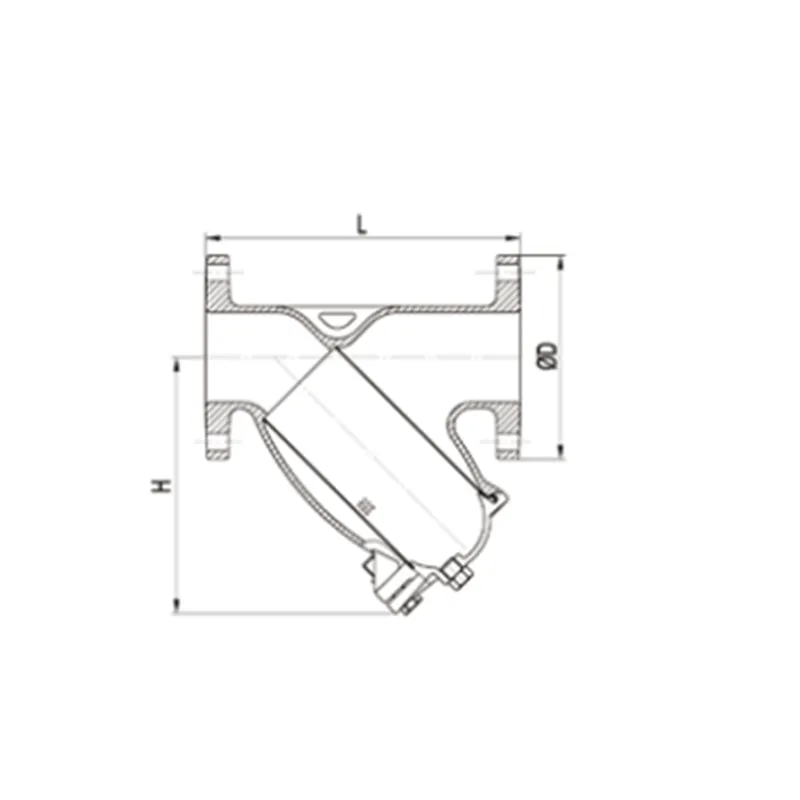
Flanged Y Strainer Size Chart