.png)
.png)


Foot Check valve
Foot Check valve Definition and Components
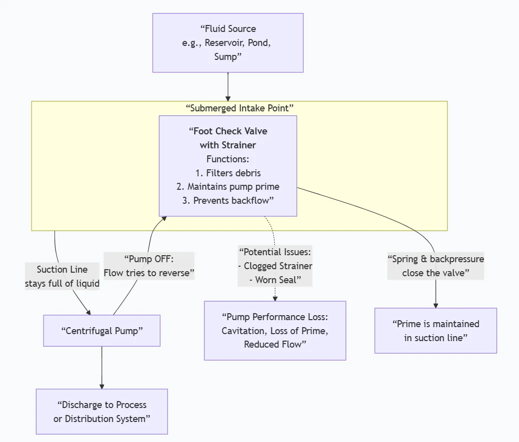
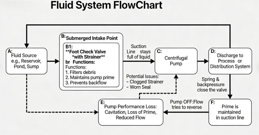
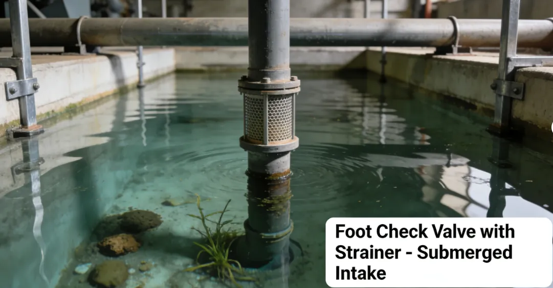
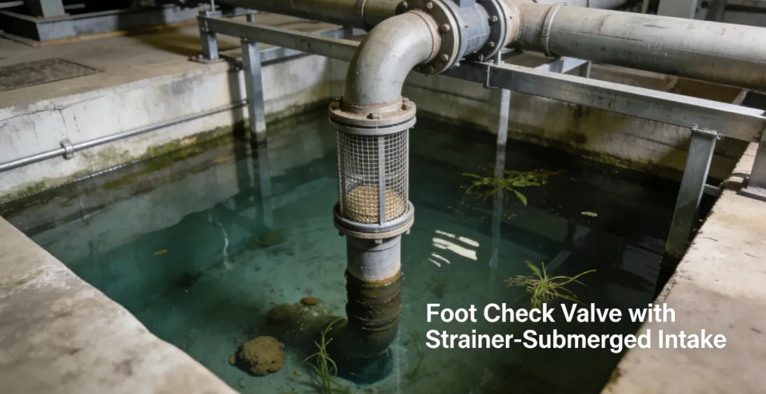
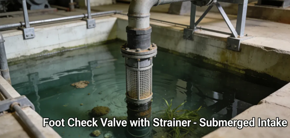
A Foot Check Valve, also known as a Foot Valve or Suction Check Valve, is a specialized type of spring-assisted check valve combined with a strainer, installed at the suction inlet of a pump (submerged in the fluid source). Its primary purpose is to maintain the pump's prime (the liquid column in the suction line) by preventing backflow when the pump shuts off.
Check Valve with Strainer Key Terminology:
- Foot/Suction Valve:Indicates its location at the "foot" or inlet end of a pump's suction line.
- Priming Function:Its core role is to keep the suction line and pump casing full of liquid, allowing the pump to start efficiently.
- Integral Strainer:Includes a screen to prevent debris from entering the pump.
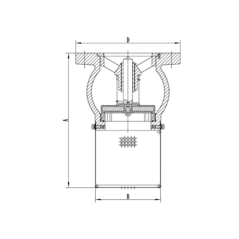
Fire Check Valve Main Parts:
- Valve Body: Housing, typically with a threaded (NPT, BSP) or flanged connection for the suction pipe.
- Disc or Poppet: The closure member that seals against the seat.
- Spring: Ensures positive closure of the disc, allowing installation in any orientation (usually vertical).
- Seat: Resilient (rubber) or metal sealing surface.
- Strainer Basket/Screen: Perforated or mesh screen surrounding the valve body to filter debris.
- Housing/Cage: Encases the strainer screen, often with a large surface area for low intake velocity.
Role, Characteristics, and Application Scenarios of Foot Check valve in Pipelines
Functions:
- Prime Retention:Keeps the suction line and pump casing filled with liquid after pump shutdown.
- Debris Filtration:The integral strainer protects the pump impeller from clogging or damage.
- Backflow Prevention:Acts as a check valve, preventing fluid from draining back to the source.
Operational Features:
- Spring-Loaded for Any Orientation:The internal spring allows installation in vertical or horizontal suction lines, ensuring closure regardless of gravity.
- Low Inlet Loss Design:The strainer basket is designed with large open area to minimize pressure drop (cavitation risk) at the pump inlet.
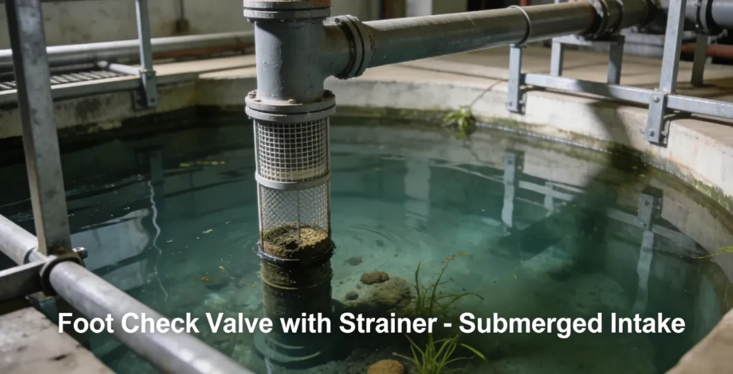
- Submersible Application:Constructed from materials suitable for continuous immersion.
- Requires Periodic Cleaning:The strainer can become clogged and must be accessible for maintenance.
Fire Fighting Valve Primary Usage Scenarios:
Exclusively used on the suction side of pumps drawing from a tank, well, sump, or other fluid reservoir. Critical for centrifugal pumps which cannot self-prime.
Scenario Diagram:
Foot Check valve Standards: Materials, Design, and Connections
| Standard Type | Primary Standard(s) | Purpose & Key Specifications |
| General Design | API 594 (Check Valves) | Provides a general basis for check valve design, though foot valves are often more application-specific. |
| Industry-Specific | AWWA A512 (Water Wells) / Hydraulic Institute Standards | AWWA A512 covers Submersible and Line-Shaft Turbine Pumps for Water Wells, often referencing foot valves. The Hydraulic Institute (HI) standards are the authoritative guide for pump system components, including intake design. |
| Material Standards | ASTM B584 C83600/C84400 (Bronze) - Common for water. | Material choice is critical for corrosion resistance in submerged service. Bronze and SS are most common. |
| ASTM A276 304/316 SS (Stainless Steel) - For corrosive fluids. | ||
| ASTM A536 (Ductile Iron) - Epoxy-coated for water. | ||
| Elastomers: ASTM D2000 (EPDM, NBR, FKM). | ||
| Connection Standard | ASME B1.20.1 (NPT Thread) - Most common. | Threaded connections dominate. Must match the pump suction port or suction pipe. |
| ISO 228-1 (BSPP/G Thread) | ||
| ASME B16.5 (Flanged) - For large pumps. | ||
| Strainer | Perforated Screen: Hole size (e.g., 1-3 mm). | Not heavily standardized; specified by hole size or mesh count based on debris. |
| Mesh Screen: 10-20 mesh common. |
How to Select Foot Check valve
Step 1: Define System-Specific Specifications
Foot valve selection is integral to pump system design.
- Pump & System Data:Critical: Provide Pump Flow Rate (GPM/L/s), desired Strainer Inlet Velocity (<1.5 ft/s is good practice), and Net Positive Suction Head Available (NPSHa) to calculate allowable pressure drop.
- Fluid & Source:Fluid type, temperature, and presence of abrasives/solids. Specify if for potable water.
- Size & Connection:Must match pump suction port size (e.g., 3" NPT). Specify thread type.
- Materials:Based on fluid compatibility (e.g., Bronze for fresh water, 316 SS for seawater).
- Strainer Details:Specify hole size (e.g., 3/16") or mesh count based on debris to exclude.
Step 2: Source from Pump System Specialists
- Source from pump distributors, irrigation suppliers, or industrial valve suppliers specializing in pump accessories.
- Consult the pump manufacturer's recommendationfor foot valve size and type.
- Request product data showing pressure drop (head loss) curves across the valve/strainer at various flows.
Step 3: Order Validation
- For large, custom, or critical systems (e.g., large irrigation, industrial process), require a dimensional drawing for approval.
- Confirm the valve includes a robust lifting chain or cable for installation and retrieval from the sump/well.
Pre-Shipment Inspection for Export Foot Check valve and Key Considerations
Inspection Checklist:
| Category | Check Point | Acceptance Criteria |
| Documentation | 1. Material Certificate | MTR for body/disc material (e.g., bronze casting cert). |
| 2. Dimensional Drawing | For threaded valves, confirm thread type (NPT, BSP) with gauge. | |
| Physical/Functional | 3. Strainer Integrity | CRITICAL: Inspect entire strainer screen. No broken welds, holes must be uniform, mesh must be intact and securely attached. |
| 4. Spring & Seal Action | Depress the disc; it should move smoothly and return firmly. The seat should be even and undamaged. | |
| 5. Thread Inspection | Threads must be clean, undamaged, and properly lubricated/protected. | |
| 6. Material Marking | Body should be marked with material (e.g., "BRONZE") and size. | |
| Packaging | 7. Strainer Protection | The protruding strainer must be protected by a cardboard tube or custom crate to prevent crushing. |
| 8. Internal Cleanliness & Dryness | Valve interior must be clean, dry, and free of foundry sand or metal chips. |
Key Precautions for Export:
- Protect the Strainer:This is the most vulnerable part. Package the valve in a long, rigid box with internal supports to prevent any crushing force on the strainer cage. Use "DO NOT CRUSH" labels.
- Prevent Galvanic Corrosion:If the valve has dissimilar metals (e.g., bronze body, stainless spring), ensure they are dry and separated by VCI paper to prevent bimetallic corrosion during humid sea transit.
- Seal Openings:Use heavy-duty, waterproof tape (not simple masking tape) over the inlet and outlet threads to prevent moisture and contaminant ingress.
- Secure for Vertical Handling:Foot valves are long. Design the crate for vertical lifting to avoid bending. Clearly mark the top.
- Include Retrieval Accessories:If a lifting chain is part of the order, coil it securely and attach it inside the crate. Do not leave it loose to tangle or damage the valve.
Foot Check valve Size Chart