.png)
.png)


Mechanical Joint Resilient Seated OS&Y Gate Valve
Mechanical Joint Resilient Seated OS&Y Gate Valve Definition and Components
A Mechanical Joint (MJ) Resilient Seated OS&Y Gate Valve, Model 1212, is a specific type of valve designed for underground or submerged service in potable water distribution and fire protection systems. It is characterized by three key features:
- Mechanical Joint Ends:Allow for a bolted, gasketed connection to ductile iron pipe without threading or welding.
- Resilient Seat:An elastomer (rubber) seal bonded to the gate provides bubble-tight shut-off.
- OS&Y (Outside Stem & Yoke):The stem rises out of the yoke when opened, providing a clear visual indication of valve position.
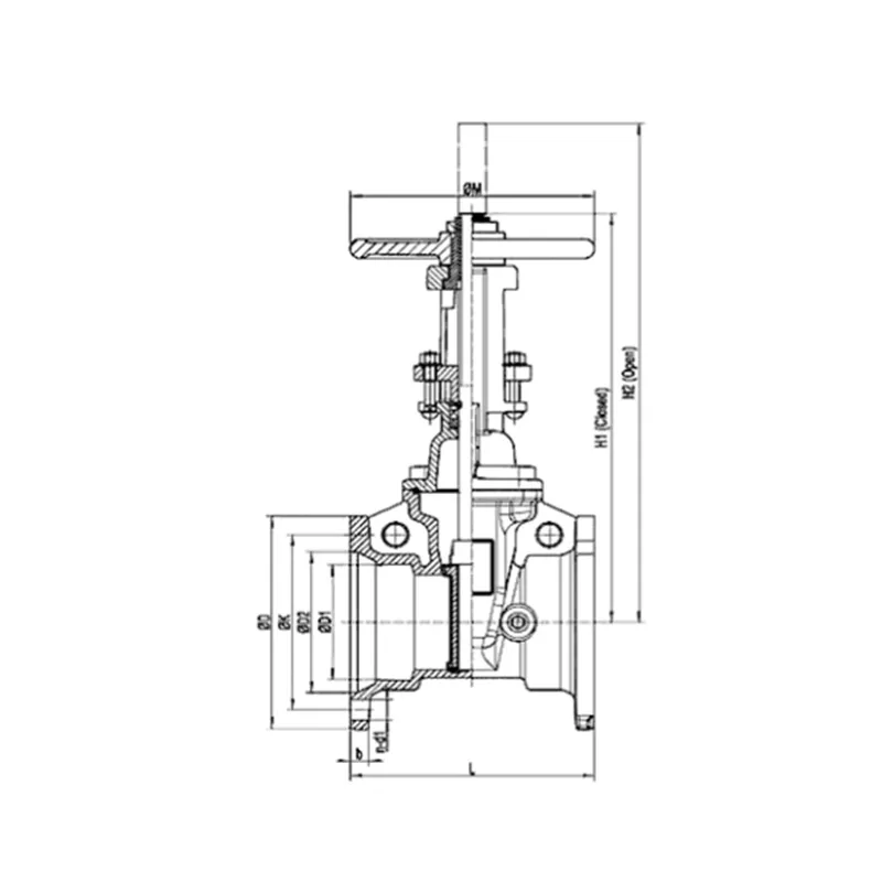
Fire valve Main Parts:
- Valve Body (with cast MJ bell ends)
- Bonnet
- Resilient-Seated Gate (disc with rubber face)
- Stem (Rising, threaded)
- Yoke Assembly (with stem nut)
- Handwheel
- MJ Gland (Follower Ring), Bolts, and Tapered Rubber Gasket
- Stem Packing (Stuffing Box)
- Seat Ring (integral or mounted in body)
- Body Drain/Test Ports (optional)
Role, Characteristics, and Application Scenarios of Mechanical Joint Resilient Seated OS&Y Gate Valve in Pipelines
Fire gate valve Functions:
- Isolation/Shut-Off:To completely stop flow in a pipeline for maintenance or emergency.
- Flow Direction:Suitable for bidirectional flow and sealing.
- System Sectionalizing:To divide a network into manageable segments.
Operational Features:
- Visual Position Indicator:The rising stem shows open/closed status at a glance.
- Bubble-Tight Sealing:Resilient seat ensures minimal leakage per AWWA standards.
- Low Operating Torque:Rubber-to-metal sealing requires less force than metal seats.
- Corrosion Resistant:Typically coated with fusion-bonded epoxy (AWWA C550).
- Field Adaptable:MJ connection accommodates minor pipe misalignment.
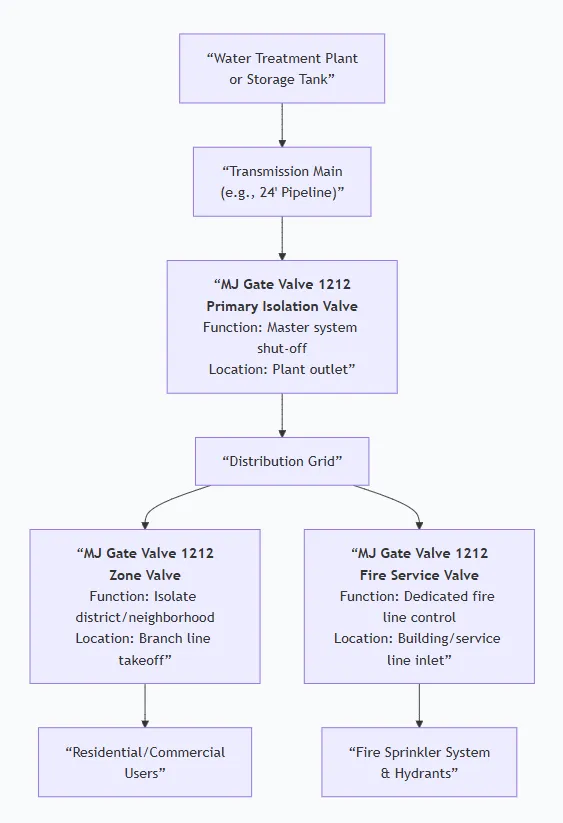
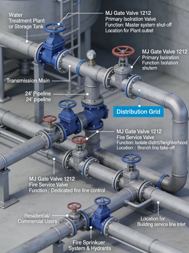
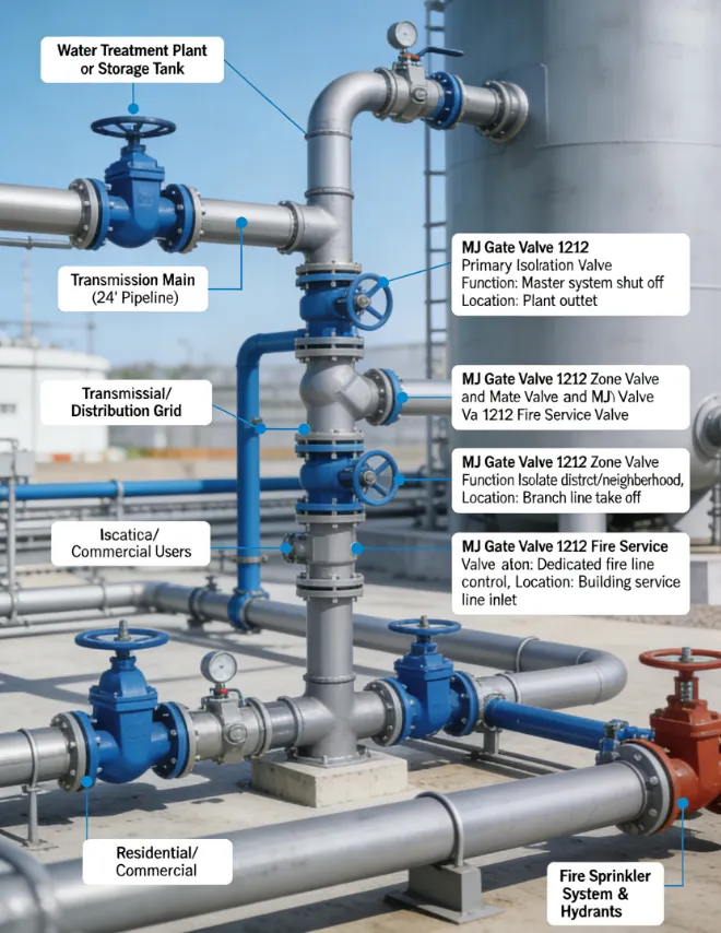
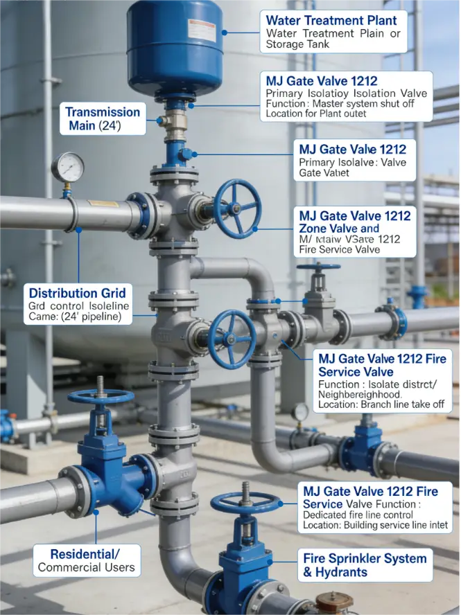
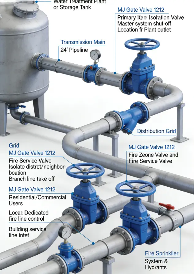
Primary Usage Scenarios:
This valve is standard in buried municipal and industrial water mains.
Scenario Diagram:
Mechanical Joint Resilient Seated OS&Y Gate Valve Standards: Materials, Design, and Connections
How to Select Mechanical Joint Resilient Seated OS&Y Gate Valve
Purchasing this specialized valve requires a technical focus to ensure proper function and longevity.
Step 1: Define Detailed Specifications
Create a procurement specification document including:
- Size & Pressure:Nominal Diameter (e.g., 12") and Pressure Class (e.g., 150 psi).
- Standards Compliance:Explicitly state: "Valve shall conform to AWWA C509."
- Materials:Specify body material (Ductile Iron per ASTM A536), epoxy coating per AWWA C550, and rubber compound (e.g., EPDM for potable water).
- Operation:Manual handwheel, or with extension stem and curb box for buried service.
- Testing & Certification:Require factory hydrostatic test reports and AWWA certification.
Step 2: Source and Evaluate Suppliers
- Identify manufacturers specializing in AWWA valves and authorized distributors.
- Request detailed submittals: product cut sheets, dimensional drawings, material certifications, and test reports.
- Evaluate based on technical compliance, project history, lead time, and cost.
Step 3: Quality Assurance & Logistics
- Consider third-party inspection (e.g., SGS, BV) for large orders.
- Finalize packaging (export crates) and documentation requirements (detailed packing lists, manuals, certificates).
Pre-Shipment Inspection for Export Valves and Key Considerations
OS&Y Gate Valve Specifications
Key Precautions for Export:
- Moisture Control:Ensure valve is completely dry and include desiccant bags inside packaging.
- Impact Protection:Use heavy-duty metal or plastic caps on MJ ends, secured with bolts. Protect the stem and handwheel with foam or cardboard.
- Secure Packing:Crate must prevent any movement during transit. Use hardwood skids and adequate blocking.
- Clear Marking:Label crates with item number, gross weight, handling symbols ("Keep Dry," "Top Lift," "This Side Up").
- Documentation Pack:Place a waterproof envelope containing copies of all critical documents (MTRs, test reports, manual) inside the crate.