.png)
.png)


Pressure Reducing Valve
Pressure Reducing Valve Definition and Components
Pressure Reducing Valve (PRV) is an automatic control valve that maintains a constant, pre-set downstream pressure regardless of fluctuations in upstream pressure or flow demand. It reduces higher inlet pressure to a stable, lower outlet pressure.
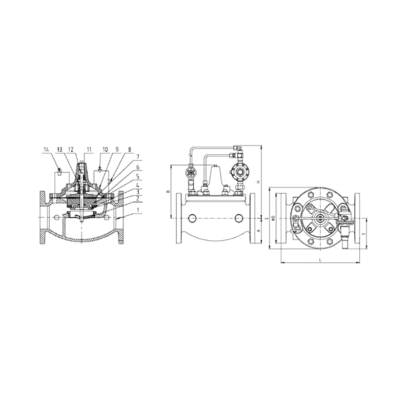
Fire Sprinkler System Pressure Reducing Valve Main Components:
- Valve Body - Main housing with inlet and outlet connections
- Diaphragm Assembly - Pressure-sensing element that controls valve opening
- Control Spring - Adjustable spring that sets desired outlet pressure
- Pilot System - In small PRVs: internal pilot; in large PRVs: external pilot valve
- Main Valve Plug/Seat - Controls flow area based on pressure signals
- Strainer - Protects pilot system from debris
- Pressure Gauges - Upstream and downstream pressure indicators
- Bypass Valve - Manual bypass for maintenance (optional)
- Adjustment Mechanism - Spring adjuster for pressure setting
- Check Valve - Prevents backflow (in some designs)
Role, Characteristics, and Application Scenarios of Pressure Reducing Valve in Pipelines
Fire Sprinkler Pressure Reducing Valve Primary Functions:
- Pressure Regulation: Maintains constant downstream pressure
- Flow Control: Adjusts opening based on demand while maintaining pressure
- System Protection: Prevents overpressure damage to downstream equipment
- Energy Conservation: Reduces water hammer and excessive flow
Operational Features:
- Self-Controlled Operation: Automatic response to pressure changes
- Adjustable Set Point: Field-adjustable within design range
- Fail-Safe Design: Typically fails open or in last position
- Accurate Control: ±5% pressure maintenance typical
- Wide Rangeability: Can handle varying flow rates
Application Scenarios:
- High-Rise Buildings: Zone pressure reduction in tall structures
- Municipal Water Systems: District pressure management
- Industrial Processes: Constant pressure supply to equipment
- Fire Protection Systems: Pressure control for sprinklers/hydrants
- Irrigation Systems: Pressure management for different zones
Pressure Reducing Valve Standards: Materials, Design, and Connections
Material Standards:
- Body/Bonnet: Ductile Iron (ASTM A536), Bronze (ASTM B584), Stainless Steel 316
- Diaphragm: EPDM, NBR, Viton based on fluid compatibility
- Internal Parts: Bronze, Stainless Steel 304/316
- Springs: Stainless Steel 302/316
- Seats/Plugs: Stainless steel with resilient seals
Fire Valve Design Standards:
- AWWA C511: Reduced Pressure Principle Backflow Prevention Assemblies
- ASSE 1003: Performance Requirements for Water Pressure Reducing Valves
- EN 1567: Building valves - Water pressure reducing valves
- FM/UL: For fire protection applications
- ISO 5208: Industrial valves - Pressure testing
Connection Standards:
- Flanged: ANSI B16.1 Class 125/150, EN 1092-2 PN10/PN16
- Threaded: NPT (ANSI B1.20.1) or BSPT (ISO 7-1)
- Grooved: Per AWWA C606
- Typical Sizes: ½" to 12" (DN15 to DN300)
- Pressure Ratings: 150-300 PSI standard, up to 600 PSI available
How to Select Pressure Reducing Valve
Purchasing Steps:
Technical Specification:
- Maximum inlet pressure
- Desired outlet pressure range
- Flow rate requirements (min/max)
- Fluid type and temperature
- Required materials (based on fluid compatibility)
- Accuracy requirements (±% pressure control)
Supplier Evaluation:
- Manufacturer certifications (ISO 9001, UL/FM)
- Experience with similar applications
- Technical support availability
- Spare parts availability
- Lead time and delivery reliability
Documentation Requirements:
- Performance curves (flow vs. pressure)
- Material certifications
- Factory test reports
- Installation and maintenance manuals
- Dimensional drawings
Commercial Considerations:
- Lead Time: 4-12 weeks depending on size
- Payment Terms: Typically 30% deposit
- Warranty: 1-3 years standard
- Shipping: FOB or CIF terms
- MOQ: Usually 1 unit
Pre-Shipment Inspection for Export Pressure Reducing Valve and Key Considerations
Inspection Checklist:
| Area | Procedure | Acceptance Criteria |
| Visual | Complete examination | No damage, proper markings |
| Dimensional | Flange/thread measurement | Per order specifications |
| Material | Verify material certs | Match PO requirements |
| Pressure Test | Shell test @ 1.5脳WP | No leaks for 2 minutes |
| Functional Test | Pressure regulation test | Maintains set pressure ±5% |
| Response Test | Flow change simulation | Stable pressure recovery |
| Adjustment | Spring adjustment check | Smooth operation, proper range |
| Coating | Thickness measurement | Proper coverage |
Export Precautions:
- Complete Drying: After hydro testing, full disassembly and drying
- Corrosion Protection: VCI paper on all internal parts
- Spring Protection: Locking mechanism to prevent fatigue during transport
- Diaphragm Protection: Proper packaging to prevent ozone damage
- Documentation: Complete certificate package including calibration reports
Real-World High-Rise Application:
In this 50-story condominium, three identical PRV stations create pressure zones to ensure:
- Equal Pressure for All Residents: Whether on floor 5 or floor 45, every unit receives 45 PSI
- Automatic Load Response: During morning shower peaks, PRVs automatically open wider to maintain pressure
- Energy Efficiency: By reducing pressure from 80 PSI to 45 PSI, the system saves pump energy and reduces water consumption
- System Protection: Prevents excessive pressure that could damage faucets, appliances, and piping
The bypass valve at each station allows maintenance without interrupting water service. The isolation valves enable easy removal for servicing. Pressure gauges on both sides allow monitoring and troubleshooting.
Key Performance Indicators:
- Pressure Stability: Maintains 45 PSI ±5% under all flow conditions
- Response Time: Adjusts to load changes within 2-5 seconds
- Turndown Ratio: Can handle flows from 5% to 100% of design capacity
- Accuracy: Typically ±2-5% of set point
- Reliability: 5-10 year service life with proper maintenance
This installation represents best practices in high-rise water system design, providing reliable, efficient pressure control that improves resident comfort while reducing operating costs and maintenance requirements.
Pressure Reducing Valve Size Chart
| Dimensions | Pressure rating | Size(mm) | |||||||
| DN | inch | psi | Φ D
|
L | H | A | B | C | E |
| 50 | 2 | 300 | 152 | 230 | 294 | 82.5 | 152 | 155 | 134 |
| 65 | 2-1/2 | 300 | 178 | 290 | 298 | 92.5 | 170 | 190 | 134 |
| 80 | 3 | 300 | 191 | 310 | 310 | 100 | 197 | 233 | 134 |
| 100 | 4 | 300 | 229 | 360 | 320 | 110 | 234 | 270 | 134 |
| 150 | 6 | 300 | 279 | 500 | 352 | 158 | 311 | 378 | 134 |
| 200 | 8 | 300 | 343 | 610 | 382 | 190 | 377 | 496 | 134 |