.png)
.png)


 Model ZCV-A.png")
Riser Manifold Model: ZCV-A
The riser manifold ZCV.A is designed to serve as the central connection point between the water supply and the fire sprinkler piping. lt integrates various components to control, monitor, and test the system.
Riser Manifold Model: ZCV-A Features
Compact, light weight design
Space Efficiency
Schedule 40 welded body (2" through 8")
Vertical or horizontal installation
Grooved components enable universal application
Assembled with FM&UL Approved components
Riser Manifold Model: ZCV-A Applications in Fire Protection
- Commercial Buildings: Office buildings, shopping malls, and warehouses use this assembly to ensure a reliable and
- compact fire protection solution.
- Residential High-Rises: lt is used in multi-family residences to maintain compact sprinkler riser configurations
- Industrial Facilities: ldeal for facilities with limited space but a need for robust fire protection systems
Riser Manifold Model: ZCV-A Description
The Riser Manifold ZCV-A is an assembled unit complete with water flow switch, pressure gauge, and test&drain as a cost-effective system riser or floor control assembly.
Test and Drain Valve installed on the riser manifold provides a simplified means for testing of water flow alarm devices and draining for feed mains. Moreover, test and drain valve reduces the risk of leaks with robust, globe-style design and offers integrated pressure relief, which has an adjustable range of 175 psi to 310 psi. Excess system pressure is exhausted intemally through the valve’s drain outlet.
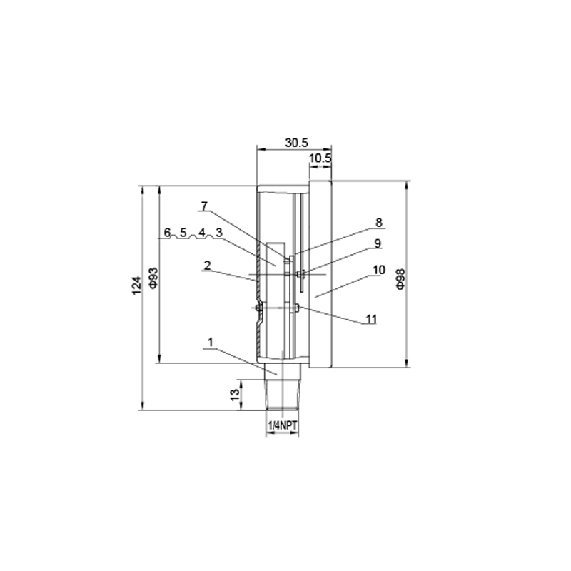
Riser Manifold Model: ZCV-A Dimensions
| Valve Size | End Connections | Material | End to End Take Out | Drain Size |
| 2"(50mm) | Threaded/Grooved | Schedule 40 Steel | 210mm/330mm | 1"(25mm) |
| 2-½(65mm) | Grooved | Schedule 40 Steel | 330mm | 1-¼(32mm) |
| 3"(80mm) | Grooved | Schedule 40 Steel | 330mm | 1-¼"(32mm) |
| 4"(100mm) | Grooved | Schedule 40 Steel | 330mm | 2"(50mm) |
| 6"(150mm) | Grooved | Schedule 40 Steel | 330mm | 2"(50mm) |
| 8"(200mm) | Grooved | Schedule 40 Steel | 330mm | 2"(50mm) |
Riser Manifold Model: ZCV-A Structure Character
| NO. | Name | Material | QTY |
| 1 | Water Flow Switch | Spare Parts Of Water Flow Switch | 1 |
| 2 | Connection Pipe | Steel/ss304 | 1 |
| 3 | Three-way Valve | Spare Parts Of Three-way Valve | 1 |
| 4 | Pressure Gauge | Spare Parts Of Gauge | 1 |
| 5 | Test&drain Valve | Spare Parts Of Test&drain Valve | 1 |
Riser Manifold Model: ZCV-A Definition and Components
The Riser Manifold Model: ZCV-A is a pre-fabricated, modular valve assembly designed as the central control and distribution point for water-based fire protection systems in both commercial and residential buildings. While "ZCV-A" is a specific manufacturer's model number, this type of assembly typically integrates multiple critical functions into a single, compact unit installed at the base of the system's vertical riser pipe.
Valve Manifold Main Parts (Typical Configuration):
- Main Inlet Valve: A gate or butterfly valve to isolate the entire system from the water supply.
- Main Check Valve: Prevents backflow of system water into the supply line.
- System Riser Outlet: The vertical pipe connection that feeds the building's sprinkler or standpipe network.
- Fire Department Connection (FDC) Inlet: A dedicated threaded branch for connecting the exterior FDC piping.
- FDC Check Valve: A swing-check valve on the FDC inlet to prevent system water from discharging out to the FDC.
- Drain Valve: A ball or gate valve for draining the manifold and riser.
- Test & Trim Valves: Multiple small valves for testing the main check valve, draining, and metering flow.
- Pressure Gauge Taps: Connections for installing supply and system pressure gauges.
- Alarm Valve Connection (if applicable): An outlet for connecting to a water flow alarm device (like a vane switch or pressure switch).
- Rugged Steel Framework: A structural frame that supports and aligns all components.
Role, Characteristics, and Application Scenarios of Riser Manifold Model: ZCV-A in Pipelines
Fire Valves Functions in Pipelines:
- Centralized Control: Provides a single location to isolate, test, and drain the primary fire protection system riser.
- Backflow Prevention: The main check valve protects the public water supply.
- FDC Integration: Properly channels supplemental water from fire department pumpers into the system riser.
- System Monitoring: Allows for easy installation of test ports and gauges to monitor supply and system pressure.
- Simplified Installation: Pre-assembled and tested unit reduces field labor and potential installation errors.
Operational Features:
- Compact, Pre-Piped Design: All components are mounted and piped on a common frame.
- Standardized Configuration: Built to comply with common code requirements (NFPA 13, 13R, 14).
- Multiple Outlet Options: May include taps for auxiliary systems like a domestic water supply or a fire pump test header.
- Labeled Components: Valves and connections are clearly labeled for easy identification by inspectors and maintenance personnel.
Riser Manifold Model: ZCV-A Standards: Materials, Design, and Connections
Material Standards:
- Body of Valves: Ductile Iron (ASTM A536) or Bronze (ASTM B62).
- Pipe & Fittings: Carbon Steel (ASTM A53) or Stainless Steel.
- Frame: Carbon Steel, painted or galvanized.
- Internal Trim: Stainless Steel (AISI 304/316) for stems, clappers, and springs.
- Seats & Seals: EPDM or Buna-N rubber.
Design & Performance Standards:
- UL/FM Standards: Individual valves (check valves, gate valves) must be UL/FM approved. The assembly itself may be listed as a package under UL 260 or similar for Dry Pipe and Deluge Valves or as a pre-assembled "Riser Manifold."
- NFPA 13 & 14: Govern the design requirements, valve types, and arrangement of components.
- ASSE 1013 / AWWA C508: Standards for check valves used in fire protection.
- Pressure Rating: Standard working pressure is 175 psi or 250 psi.
Connection Standards:
- Main Inlet/Outlet: Typically flanged (ANSI B16.1 Class 125) or grooved (AWWA C606) for commercial sizes (4", 6", 8"). Residential models may use threaded (NPT) connections (2", 2.5", 3").
- FDC Inlet: Threaded (NPT) to connect to the FDC piping, usually 2.5" or larger.
- Auxiliary Connections (Drain, Test): Threaded (NPT), commonly 1", 1.5", or 2".
How to Select Riser Manifold Model: ZCV-A
Purchasing Guide:
Provide Complete System Specifications:
- Water Supply Data: Static/Residual pressure, available flow (from water authority report or hydraulic calc).
- System Type: NFPA 13 (commercial), NFPA 13R (residential), or NFPA 14 (standpipe).
- Pipe Sizes: Required inlet size (from water supply) and riser outlet size (to building system).
- Required Features: Specify if needed for combined sprinkler/standpipe, if a fire pump is upstream, or if a specific alarm device (e.g., pressure switch) is to be mounted.
Request Detailed Submittal Package:
- Since this is a specific model (ZCV-A), request the manufacturer's technical data sheet, cut sheet, and detailed diagram for that exact model.
- Require a listing/approval guide showing UL or FM certification for the entire assembled manifold, not just its parts.
- Request a material list and dimensional drawing for approval by the project's fire protection engineer.
Supplier Selection:
- Source directly from the manufacturer of the ZCV-A model or their authorized distributor.
- Clarify lead time, as these are often built-to-order.
- Confirm if the price includes pre-shipment hydrostatic testing and certification.
Pre-Shipment Inspection for Export Riser Manifold Model: ZCV-A and Key Considerations
Inspection Checklist: