.png)
.png)


 Model ZCV-B.png")
Riser Manifold Model: ZCV-B
The riser manifold ZCV-B is designed primarily for use as a floor or zone control assembly in NFPA 13 or 13R applications. t
can also function as a conventional wet system riser.
Riser Manifold Model: ZCV-B Features
Compact, light weight design
Space Efficiency
Schedule 40 welded body (2" through 8")
Vertical or horizontal installation
Grooved components enable universal application
Assembled with FM&UL Approved components
Riser Manifold Model: ZCV-B Applications in Fire Protection
Commercial Buildings: Office buildings, shopping malls, and warehouses use this assembly to ensure a reliable and
compact fire protection solution.
Residential High-Rises: lt is used in multi-family residences to maintain compact sprinkler riser configurations
Industrial Facilities: ldeal for facilities with limited space but a need for robust fire protection systems
Riser Manifold Model: ZCV-B Description
The Manifold Riser ZCV-B is assembled with butterfly valve, check valve, water flow switch, pressure gauge, and test&drain as a costeffective system riser or floor control assembly.
Test and Drain Valve installed on the riser manifold provides a simplified means for testing of water flow alarm devices and draining for feed mains. Moreover, test and drain valve reduces the risk of leaks with robust, globe-style design and offers integrated pressure relief, which has an adjustable range of 175 psi to 310 psi. Excess system pressure is exhausted intemally through the valve’s drain outlet.
Riser Manifold Model: ZCV-B Dimensions
| Valve Size | End Connections | Material | End to End Take Out | Drain Size |
| 2"(50mm) | Threaded/Grooved | Schedule 40 Steel | 210mm | 1"(25mm) |
| 2-½(65mm) | Grooved | Schedule 40 Steel | 200mm | 1-¼(32mm) |
| 3"(80mm) | Grooved | Schedule 40 Steel | 200mm | 1-¼"(32mm) |
| 4"(100mm) | Grooved | Schedule 40 Steel | 240mm | 2"(50mm) |
| 6"(150mm) | Grooved | Schedule 40 Steel | 250mm | 2"(50mm) |
| 8"(200mm) | Grooved | Schedule 40 Steel | 330mm | 2"(50mm) |
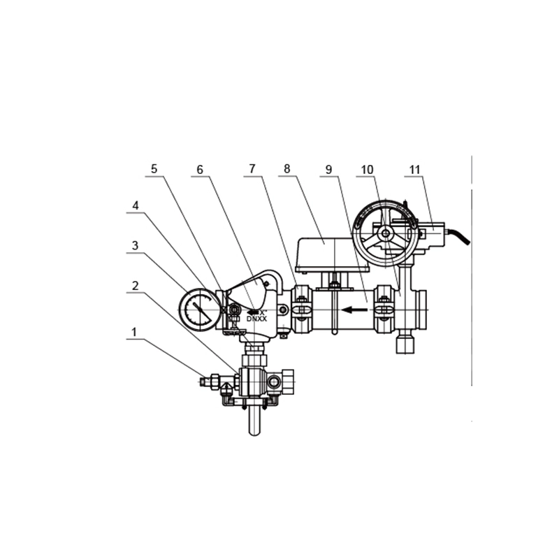
Riser Manifold Model: ZCV-B Structure Character
| NO. | Name | Material | QTY |
| 1 | Pressure Relief Valve | Spare Parts of Pressure Relief Valve | 1 |
| 2 | Test&drain Valve | Spare Parts of Test&drain Valve | 1 |
| 3 | Pressure Gauge | Spare Parts of Gauge | 1 |
| 4 | Connector | SS304 | 1 |
| 5 | Three-way Valve | Spare Parts of Three-way Valve | 1 |
| 6 | Groove Check Valve | Spare Parts of Check Valve | 1 |
| 7 | Groove Coupling | Spare Parts of Groove Coupling | 1 |
| 8 | Water Flow Switch | Spare Parts of Water Flow Switch | 1 |
| 9 | Connection Pipe | Steel/SS304Spare Parts of Butterfly Valve | 1 |
| 10 | Groove Butterfly Valve | Spare Parts of Gear Box | 1 |
| 11 | Signal Gear Box | Spare Parts of Pressure Relief Valve | 1 |
Riser Manifold Model: ZCV-B Definition and Components
The Riser Manifold Model: ZCV-B is an advanced, pre-fabricated control assembly designed to serve as the central command and distribution point for two separate fire protection systems—typically a combination like a sprinkler system and a standpipe system—from a single water supply inlet. Building upon the ZCV-A concept, the ZCV-B model incorporates dual, independent control and distribution pathways.
Valve Manifold Main Parts (Typical Configuration):
- Common Inlet Header: Receives water from the primary supply (city main or fire pump).
- Main Isolation Valve: A single master gate or butterfly valve to shut off supply to both systems.
- Dual System Manifold: Splits the flow into two distinct branches, each containing:
- Individual System Isolation Valve: Allows independent shutdown of System 1 or System 2.
- Individual Check Valve: Prevents backflow from each system into the common header or the other system.
- System Riser Outlet: Connection to the dedicated vertical riser pipe for that system (e.g., Sprinkler Riser, Standpipe Riser).
- Fire Department Connection (FDC) Inlet: A dedicated inlet for supplemental water supply, often routed to a common manifold that can feed both systems.
- Dual Test and Drain Assemblies: Each system branch has its own set of drain valves, test headers, and pressure gauge taps for independent testing and maintenance.
- Alarm Valve Connections: Provisions for connecting water flow alarm devices (e.g., pressure switches) for each system.
- Structural Steel Framework: A rigid frame supporting and aligning all components.
Role, Characteristics, and Application Scenarios of Riser Manifold Model: ZCV-B in Pipelines
Fire Valves Functions in Pipelines:
- Centralized Dual-System Control: Provides a single, organized location to control, isolate, and test two independent fire protection systems.Cross-Contamination Prevention: Individual check valves prevent water from one system (e.g., stagnant standpipe water) from flowing back into the other (e.g., sprinkler system).
- Efficient FDC Integration: Allows fire department pumpers to supply both systems simultaneously via a single FDC connection point.
- Independent Maintenance & Testing: Enables one system to be drained, tested, or repaired while the other remains in service.
- Space Optimization: Condenses the valving for two systems into one compact, pre-engineered assembly.
Operational Features:
- Modular, Dual-Branch Design: Clear separation of control for System 1 and System 2.
- Common Supply, Independent Operation: Systems share the supply but can be operated and maintained separately.
- Comprehensive Testing Ports: Full suite of drains, test valves, and gauge taps for each system to meet NFPA testing requirements.
- Pre-Piped & Pre-Tested: Factory assembled and pressure tested, ensuring reliability and reducing field labor.
Common Scenarios:
- Commercial/High-Rise Buildings: Where combined sprinkler (NFPA 13) and standpipe (NFPA 14) systems are mandated.
- Mixed-Use Residential Towers (NFPA 13R & Standpipe): Common in mid-to-high-rise residential buildings.
- Industrial Facilities: Protecting different hazard areas with separate system requirements from a single main.
- Any project requiring two distinct water-based fire protection systems fed from one source.
- Scenario Diagram: ZCV-B Manifold for a Combined Sprinkler & Standpipe System
Riser Manifold Model: ZCV-B Standards: Materials, Design, and Connections
Material Standards:
- Body of Valves: Ductile Iron (ASTM A536) with epoxy coating, or Bronze (ASTM B62).
- Piping & Fittings: Schedule 40 Carbon Steel (ASTM A53) for primary lines.
- Framework: Structural Steel (ASTM A36), painted.
- Internal Trim: Stainless Steel (AISI 304/316) for all moving parts (stems, clappers).
- Seats & Seals: EPDM for standard water service.
Design & Performance Standards:
- UL/FM Standards: All individual control valves and check valves must be UL Listed (e.g., UL 429, UL 312) or FM Approved. The assembled manifold should have a package listing (e.g., per UL 260) or be engineered per listed components' guidelines.
- NFPA 13 & NFPA 14: Govern the design, valving requirements, and interconnections for sprinkler and standpipe systems respectively.
- ASSE 1013 / AWWA C508: Standards for check valves.
- Pressure Rating: Standard working pressures of 175 psi or 250 psi to match system demands.
Connection Standards:
- Main Inlet: Typically flanged (ANSI B16.1 Class 125) or grooved (AWWA C606). Common sizes: 4", 6", 8".
- System Riser Outlets: Flanged or Grooved connections matching the riser pipe size (e.g., 4" for sprinkler, 6" for standpipe).
- FDC Inlet: Threaded (NPT), typically 2.5" or 4".
- Auxiliary Connections (Drains, Tests): Threaded (NPT), sizes from 1" to 2".
How to Select Such Riser Manifold Model: ZCV-B
Purchasing Guide:
Submit Comprehensive System Specifications:
- Clearly define System 1 and System 2 (e.g., Wet Sprinkler System, Class I Standpipe).
- Provide hydraulic data: Required flow (GPM) and pressure for each system at the inlet.
- Specify exact pipe sizes for: Main Inlet, Outlet to Sprinkler Riser, Outlet to Standpipe Riser.
- Detail any special requirements: Fire pump upstream, needed alarm device interfaces (pressure switch, flow switch), exterior finish.
Demand Detailed Engineering Submittals:
- Request the manufacturer's detailed cut sheet and isometric drawing for the ZCV-B model, highlighting the dual-branch configuration.
- Obtain component-specific UL/FM listings for all major valves. Request documentation proving the assembly concept complies with NFPA and local code.
- Require a material list and bill of materials for approval by the project's fire protection engineer.
Supplier and Logistics Coordination:
- Source directly from the manufacturer or a highly specialized fire protection distributor.
- Acknowledge and plan for a longer lead time, as these are complex, built-to-order assemblies.
- Confirm if factory witness testing is available or required before shipment.
Pre-Shipment Inspection for Export Riser Manifold Model: ZCV-B and Key Considerations
Inspection Checklist: