.png)
.png)


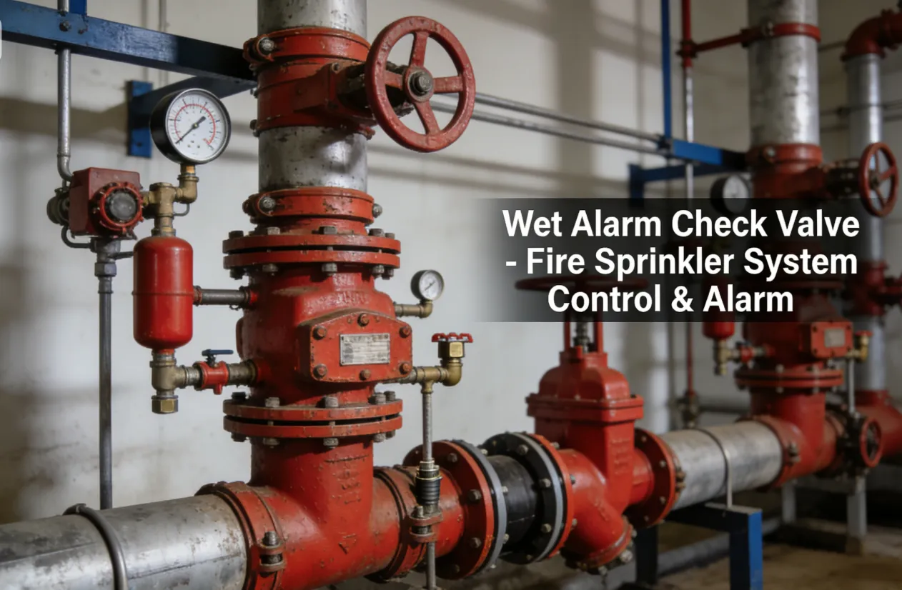
Wet Alarm Check Valve
Technical Features
- Working pressure: 300PSl
- Flange Standard: ASME/ANSI B16.1 Class 125
- ASME/ANSI B16.42 Class 150
- BS EN 1092-2PN16
- GB/T9113.1
- Groove Standard: AWWA C606
- ISO6182-12
- Working Temperature Range:4~70°C/ 39.2~158°F
- Coating Details: Epoxy coated or coating upon request
Applications in Fire Protection
This system is applicable to the places with the ambient temperature from 4'C to 70'C, This system is generally installed in the places with fire hazards. like the hotel. shopping mall. hospital. theater, office building, conference center, warehouse. high-rise building and underground garage
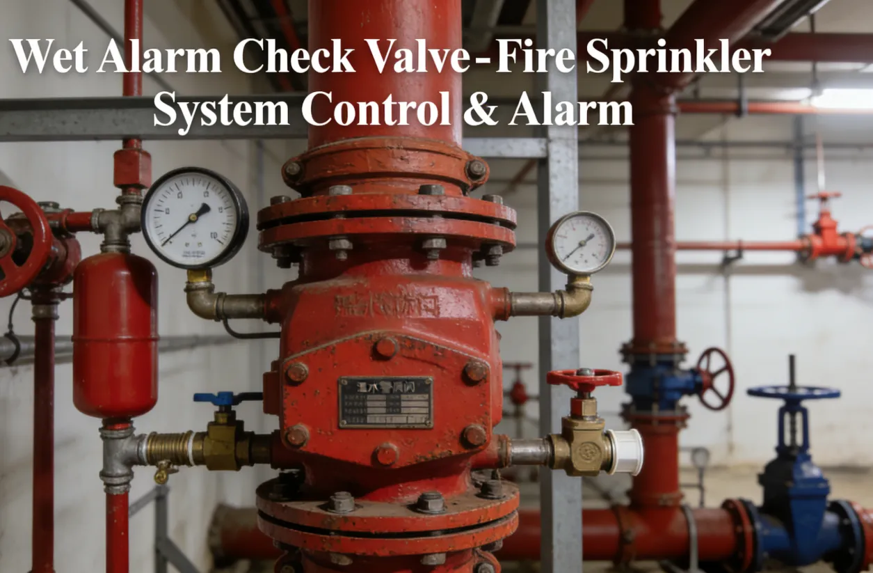
Wet Alarm Check Valve Description
Wet alarm check valve consists of wet alarm valve, retard chamber, pressure gauges, water motor alarm, pressure switch drain valve and filter etc
Alarm Check Valves act as a water flow alarm initiating device in wet pipe sprinkler systems. When water flows in the sprinkler system due to the operation of one or more automatic fire sprinklers, the alarm valve opens allowing continuous flow of water into the system, which will activate water motor bell and pressure switches
The design of the Alarm Check Valve allows for installation under both variable and constant supply pressure conditions. The valve trim incorporates a bypass between the water supply and the wet pipe system. When pressure surges in the waters supply occur, the trim allows a small amount of water to bypass the clapper limiting the potential of false alarms.
Wet Alarm Check Valve Installation
This instrument shall be installed in places where is easy to observe and access. lnstall The wet alarm valve vertically on the pipes which have been properly tested for its pressure and cleaned. Please note that the arrow for water flow direction is pointing upwards. Reserve enough operation space for repair and maintenance before installation.
Step1: Clean the system pipe network completely before installation. Ensure that the inner wall of the pipes is coated with rust-proof layer and there is no dreg or dirt in the pipes.
Step2. in order to facilitate the observation of the pipe in which an alarm occurs, it is recommended to discharge the water fro man open port or have the water discharge state easy to be observed before installation.
Step3: Check whether there is any damage at the joint between the wet alarm valve and the flange, check whether the seal is in good condition and whether the valve disc moves flexibly, carry out the leakage test with a pressure of two times of the rated working pressure. After the test, the valve disc shall be free of leakage, lf there is any problem, replace the spare parts or clear the trouble before assembling the parts together.
Step4: Turn the pressure gauge to the position where the reading is clearly visible.
Step5: The pressure switch shall be installed on the top of the delayer. This pressure switch must be installed vertically and could only be used indoors. After installation, check if it acts reliably.
Step6: The water motor alarm shall be installed on the top of the delayer, after installation, check if it acts reliably.
Step7: With the exception of support from the trim piping, the ratard chamber will also be binded by a clamp with the piping to avoid any movement or looseness
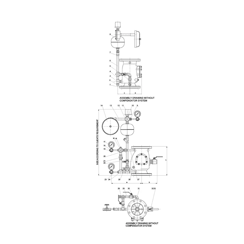
Wet Alarm Check Valve Dimensions
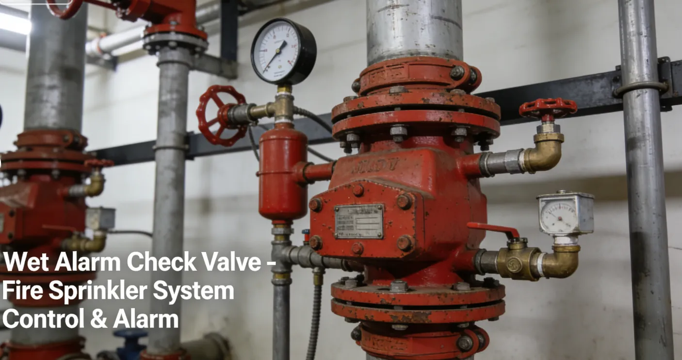
Wet Alarm Check Valve Definition and Components
A Wet Alarm Check Valve is the central control and monitoring assembly for a wet-pipe fire sprinkler system. It is a specialized, multi-functional valve that serves three critical purposes: (1) it acts as a check valve to hold system water pressure; (2) it provides a waterflow alarm signal; and (3) it allows for system testing and drainage.
Fire Sprinkler Alarm Check Valve Key Terminology:
- Wet:Indicates its use in "wet-pipe" systems where the piping is constantly filled with pressurized water.
- Alarm:The valve assembly includes a port that, upon water flow, activates a hydraulic (water-driven) alarm bell or horn and an electrical pressure switch for remote signaling.
- Check Valve:Its primary valve component is a clapper-style check valve that prevents water from flowing back into the supply line, maintaining pressure on the system side.
Main Parts:
- Main Valve Body: Houses the primary clapper assembly.
- Clapper & Seat: The one-way check valve mechanism.
- Alarm Port (Retard Chamber): A small port and chamber that delays slight pressure fluctuations to prevent false alarms.
- Trim (Piping) Assembly: A network of small pipes and valves for control and testing, including:
- Alarm Line: Piping to the Water Motor Gong (Alarm Bell) and Pressure (Flow) Switch.
- Drain Valve & Test Valve: For system drainage and flow simulation testing.
- Bypass (Maintenance) Valve: Allows filling the system while the main clapper is being serviced.
- Pressure Gauges: One for supply (inlet) pressure and one for system (outlet) pressure.
- External Reset Lever/Handwheel: For manually resetting the clapper after testing or operation.
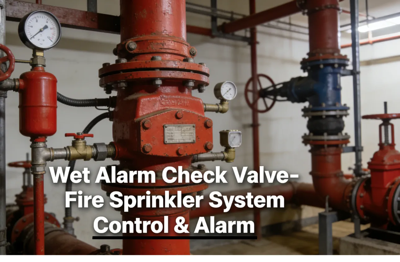
Role, Characteristics, and Application Scenarios of Wet Alarm Check Valve in Pipelines
Fire Valves Functions:
- System Shut-off: The primary on/off control for water entering the sprinkler system.
- Check Valve Function: Maintains system water pressure and prevents backflow.
- Alarm Activation: Detects water flow (from a sprinkler head opening) and mechanically activates local and remote alarms.
- System Testing & Drainage: Provides dedicated points for flow tests and system drainage.
Operational Features:
- "Wet" System Core: Always under pressure. The clapper is held closed by higher system-side pressure until a sprinkler opens.
- Alarm Activation Sequence: When a sprinkler opens, water flows, lifting the clapper. Water then flows into the alarm port, driving the Water Motor Gong (audible local alarm) and tripping the Pressure Switch (electrical signal to the fire alarm panel).
- Retard Chamber: Prevents false alarms from temporary, minor pressure surges (e.g., from city main fluctuations).
- Required Weekly/Monthly Testing: Features like the Inspector's Test Connection allow for simulating a single sprinkler head flow to test the alarm without activating the full system.
Primary Usage Scenarios:
Exclusively used as the main control valve for automatic wet-pipe fire sprinkler systems in commercial, industrial, and residential buildings where there is no risk of freezing.
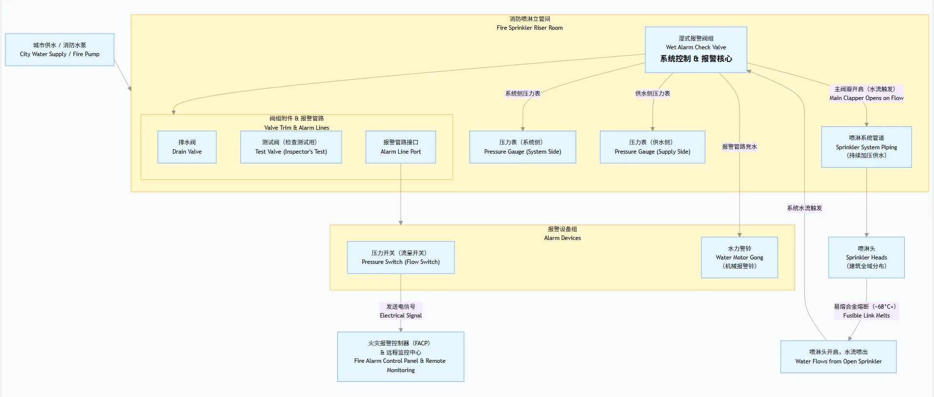
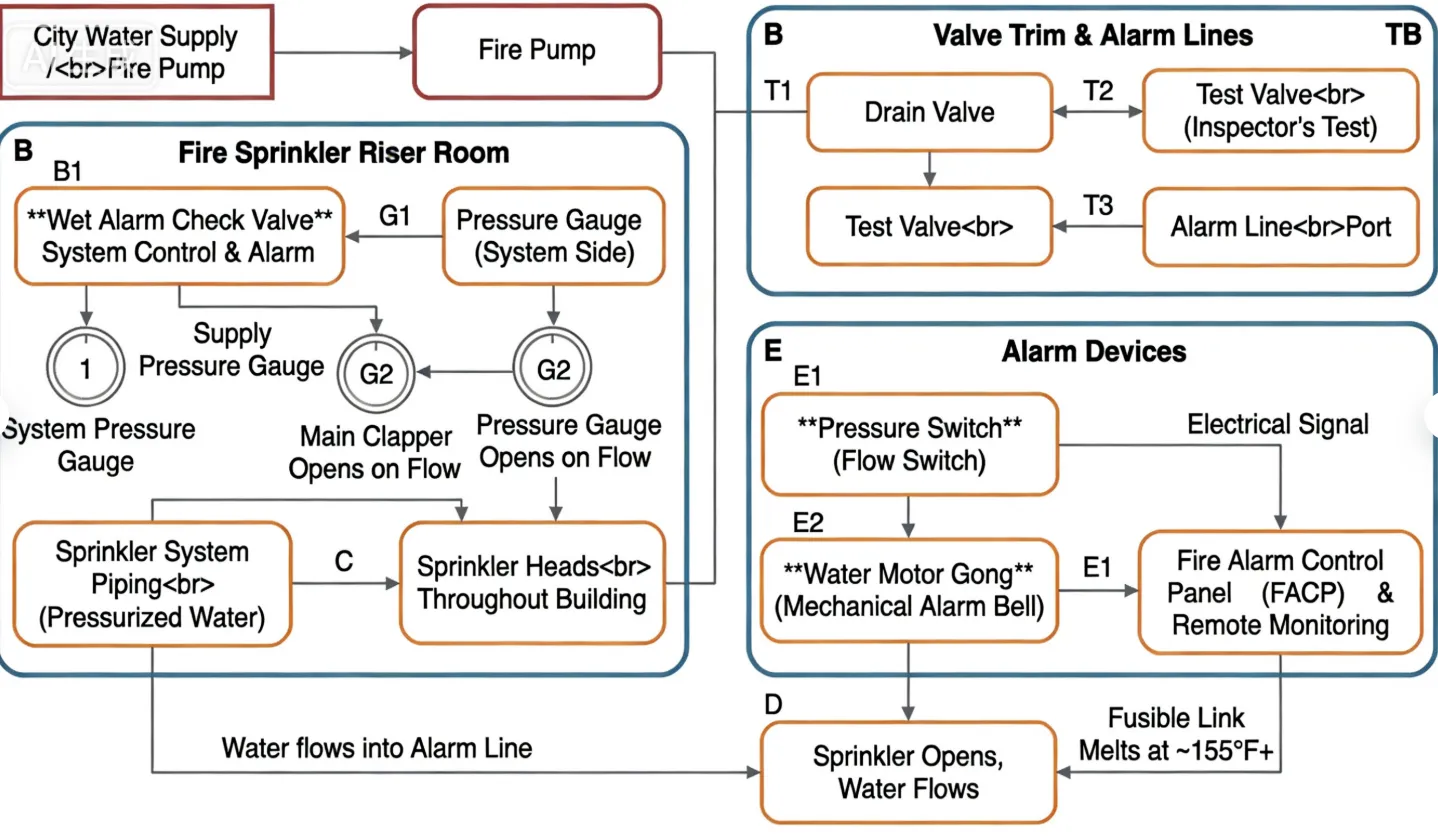
Scenario Diagram:
Wet Alarm Check Valve Standards: Materials, Design, and Connections
| Standard Type | Primary Standard(s) | Purpose & Key Specifications |
| Design & Performance | UL 260 / FM 1110 | The essential listing standards for Wet Pipe Alarm Valves in North America. Compliance is mandatory for code acceptance. |
| Fire System Code | NFPA 13 | The installation standard for sprinkler systems. Dictates valve location, sizing, alarm connections, and testing requirements. |
| Material Standards | ASTM A126 Class B (Gray Iron Body) - Common. | |
| ASTM A536 (Ductile Iron) - For higher pressure. | ||
| ASTM B584 C83600 (Bronze Trim Valves) - For corrosion resistance. | ||
| ASTM A276 (Stainless Steel Clapper & Spring) | ||
| Connection Standards | ASME B16.1 Class 125/250 (Flanged) - Most common. | Flanged connections are standard. The size is determined by the hydraulic calculation of the sprinkler system (e.g., 4", 6", 8"). |
| AWWA C110/A21.10 (Flanged Ductile Iron) - Alternative. | ||
| ASME B16.5 may be referenced for drilled flanges. | ||
| Alarm Device Standards | UL 753 (Water Motor Alarm) / UL 864 (Control Units for Pressure Switch) | Standards for the associated alarm devices. |
How to Select Wet Alarm Check Valve
Step 1: Define Specifications Based on System Design
The valve is specified by the fire protection engineer.
- Size & Pressure Rating:Determined by hydraulic calculations (e.g., 6" valve, 175 psi working pressure).
- Listing Requirement:Must specify: "UL 260 Listed and/or FM Approved Wet Alarm Check Valve."
- Connection Type:Flanged, per system drawings (e.g., ASME B16.1 Class 125).
- Trim Configuration:Specify required trim valves (drain, test, bypass) and their connection sizes (e.g., 1" NPT).
- Alarm Connections:Specify outlet size/type for the Water Motor Gong and Pressure Switch (typically 3/4" or 1" NPT).
- Include Accessories:Pressure gauges, alarm devices (gong, pressure switch), and test valves are often purchased separately but must be compatible.
Step 2: Source from Fire Protection Specialists
- Onlypurchase from authorized distributors of major fire protection valve manufacturers (e.g., Victaulic, Tyco, Reliable, Potter).
- Require a complete submittal packageincluding: UL/FM listing sheets, detailed cutaway drawings, material specifications, and trim diagram.
- Verify the submitted model is listed in the UL/FM online directories.
Step 3: Technical Review & Order
- The engineer should approve the submittal before ordering.
- Ensure the purchase order references the approved submittals and lists all required components (valve, trim kit, alarms).
Pre-Shipment Inspection for Export Wet Alarm Check Valve and Key Considerations
Inspection Checklist:
| Category | Check Point | Acceptance Criteria |
| Documentation | 1. UL/FM Listing Mark | The listing mark must be permanently affixed (cast or stamped) on the valve body. |
| 2. UL/FM Guide Card/Report | Copy of the official listing document for the exact model/configuration. | |
| 3. Hydrostatic Test Certificate | Proof of shell and seat testing at the factory. | |
| Physical/Functional | 4. Clapper Operation | The reset lever/handwheel should operate smoothly to lift the clapper. |
| 5. Trim Valve Operation | All small trim valves (drain, test) should open/close smoothly without leakage. | |
| 6. Cleanliness & Paint | Internal passages must be clean. External paint/coating should be intact. Red is standard. | |
| 7. Flange Protection | Flange faces must be undamaged and protected with wooden/plastic guards. | |
| Packaging | 8. Internal Protection | Valve must be drained completely dry. Desiccant bags should be placed inside the body. |
| 9. Component Securement | The clapper should be secured in the closed position. All trim valves should be closed. |
Key Precautions for Export:
- Complete Internal Dryness:This is critical to prevent freezing or corrosion during transit. The valve must be blown dry with air after testing. Use vapor-phase corrosion inhibitor (VCI) bags inside the valve body and trim piping.
- Secure All Internals:The clapper must be blocked or strapped to prevent movement and damage to the seat during shipping shocks.
- Protect Alarm Ports:Cap all small threaded outlets (alarm line, drain, test connections) with heavy-duty plastic plugs, not tape.
- Crate as a Unit:The main valve and its pre-assembled trim should be mounted on a common, rigid skid and crated together to maintain alignment and prevent damage to the small piping.
- Separate Box for Delicates:Pack the pressure gauges and any electronic pressure switch separately in well-cushioned boxes. Do not leave them installed on the valve for shipping.
- Mandatory Documentation Inclusion:Place a waterproof pouch containing the installation manual, test reports, and UL/FM listing card inside the main crate. This is more important than commercial documents for the installing contractor.