


Mechanical Joint Resilient Seated NRS Gate Valve with Indicator Post
Mechanical Joint Resilient Seated NRS Gate Valve with Indicator Post Definition and Components
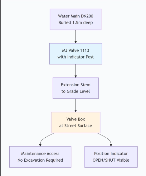
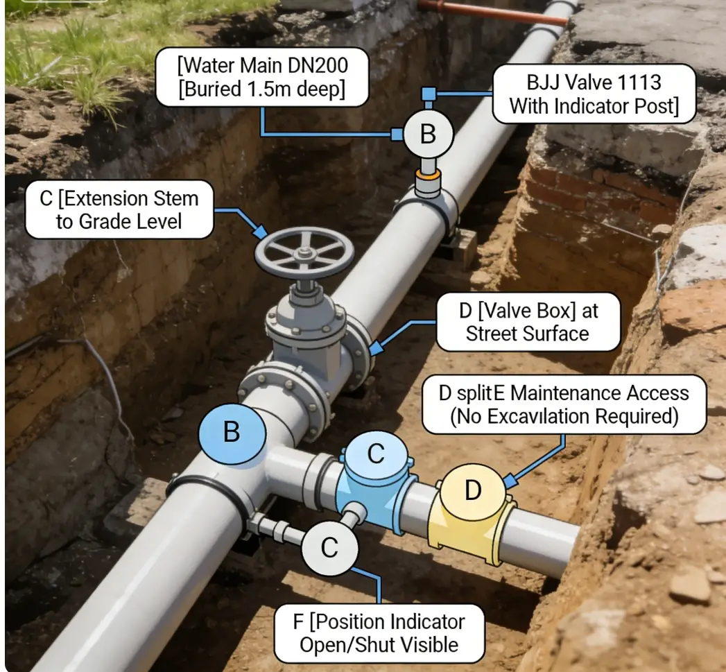
A Mechanical Joint Resilient Seated ul/fm NRS Gate Valve with Indicator Post (Model 1113) is a buried water valve that can be operated from ground level. It combines a standard mechanical joint valve with an extension stem and protective post.
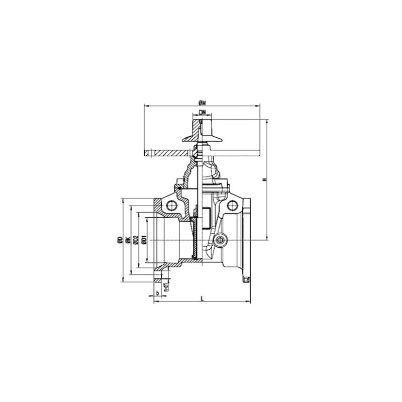
Main Parts:
- Valve body with MJ ends
- Resilient-seated gate
- Long extension stem
- Indicator post (steel pipe)
- Ground-level operating nut with position indicator
- Protective valve box/cover
Role, Characteristics, and Application Scenarios of Mechanical Joint Resilient Seated NRS Gate Valve with Indicator Post in Pipelines
Fire gate valve Functions:
- Buried pipeline isolation
- Above-ground operation
- Visual position indication
- Emergency shutdown access
Operational Features:
- No excavation needed
- Corrosion protected
- Lockable cover option
- Full port design
Fire valve Typical Applications:
- Underground water mains
- Street valve installations
- Fire protection systems
- Subdivision isolation points
Scenario Diagram:
Mechanical Joint Resilient Seated NRS Gate Valve with Indicator Post Standards: Materials, Design, and Connections
Material Standards:
- Body/Gate: ASTM A536 Ductile Iron
- Stem: ASTM A276 Stainless Steel
- Post: ASTM A53 Galvanized Steel
- Seat: EPDM (NSF/61 approved)
Design Standards:
- Primary: AWWA C509
- Pressure: 150/200 psi standard
- Burial: AWWA C550 coating
Connection Standards:
- Mechanical Joint: AWWA C111
- Pipe Compatibility: AWWA C110/C151
- End Type: MJ x MJ (both ends)
How to Select Mechanical Joint Resilient Seated NRS Gate Valve with Indicator Post
Key Steps:
- Specify: Size, pressure, post length, burial depth
- Verify Standards: AWWA C509 compliance mandatory
- Select Supplier: Experienced in buried valve packages
- Request Documents: AWWA certs, NSF/61, material reports
- Review Drawing: Confirm post length and details
Critical Specifications:
- Post length (from valve center to grade)
- Valve box type (traffic-rated or standard)
- Locking mechanism required
- Soil condition for coating selection
- Lead Time: Typically 10-16 weeks for custom extensions.
Pre-Shipment Inspection for Export Mechanical Joint Resilient Seated NRS Gate Valve with Indicator Post and Key Considerations
Documentation Check:
AWWA C509 Certificate
NSF/61 Certification
Material Test Reports (ASTM)
Hydrostatic Test Certificates
Physical Inspection:
Dimensional Verification
Post length (match order)
MJ bell dimensions
Face-to-face measurement
Pressure Testing
Shell test: 2× rated pressure
Seat test: 1.1× rated pressure
Zero leakage requirement
Operational Test
Smooth operation through extension
Indicator accuracy (open/shut)
Torque within limits
Coating Inspection
Internal epoxy: 8-12 mils thickness
External protection per spec
No holidays or defects
Export Packaging:
- Indicator post must be supported in crate
- Operating nut wrapped separately
- Valve box packaged individually
- VCI bags in valve cavity
- Desiccant for humid destinations
- Wooden crate with lifting points
Key Precautions:
Long items: Special reinforcement in container
Thread protection: Caps on all exposed threads
Climate: Extra moisture protection for humid regions
Instructions: Include detailed burial/installation guide
Final Documents for Shipment:
Commercial Invoice
Packing List
Bill of Lading
Certificate of Origin
Complete technical file (certs, reports)
Installation Manual