.png)
.png)


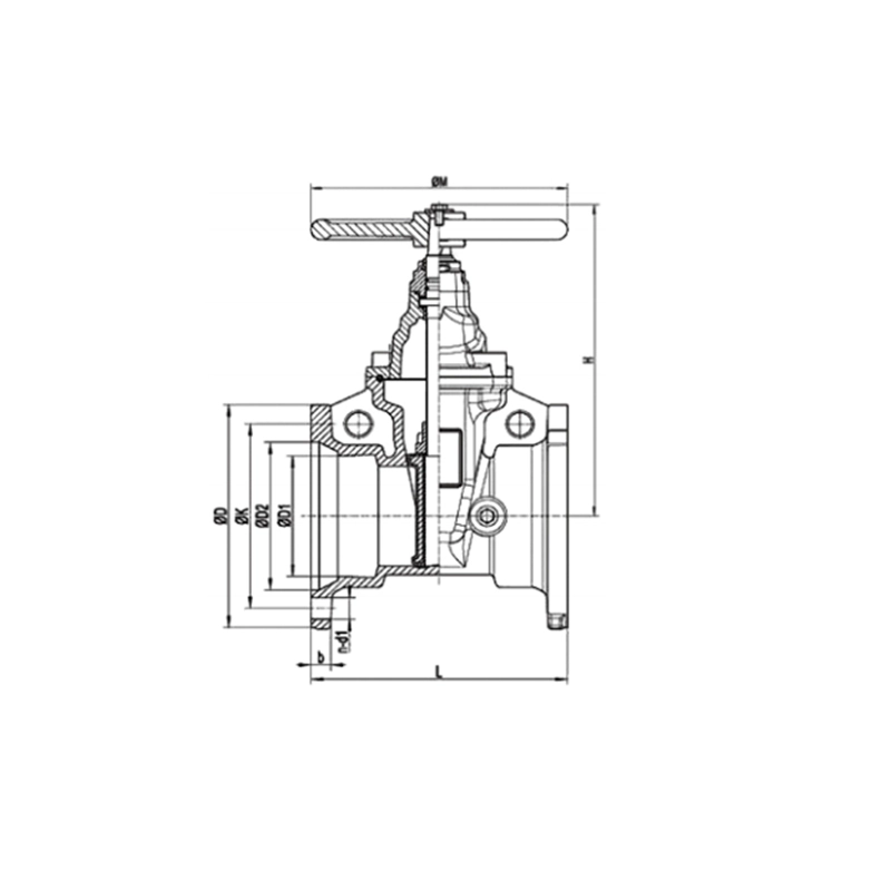
Mechanical Joint Resilient Seated NRS Gate Valves
Mechanical Joint Resilient Seated NRS Gate Valves Definition and Components
A Mechanical Joint (MJ) Resilient Seated NRS Gate Valve Model 1112 is designed by nrs gate valves supplier for ductile iron pipe systems using mechanical joint connections instead of flanges. "1112" indicates manufacturer's model (1=gate valve, 1=mechanical joint, 12=design series).
Fire gate valve Main Parts:
Body: Ductile iron with integral MJ bell ends
Gate: Ductile iron core with full rubber encapsulation (EPDM/NBR)
Stem: Stainless steel, non-rising type
MJ Connection Components: Gland, bolts, nuts, gasket
Bonnet: Bolted to body
Stem Nut & Handwheel: For manual operation
Packing System: Stem seals
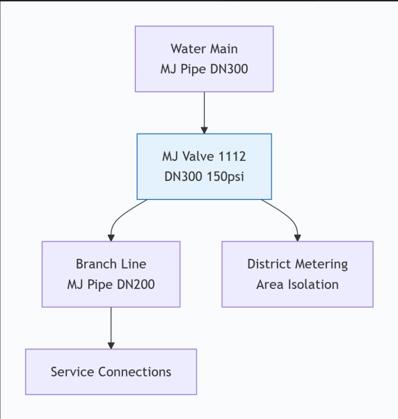
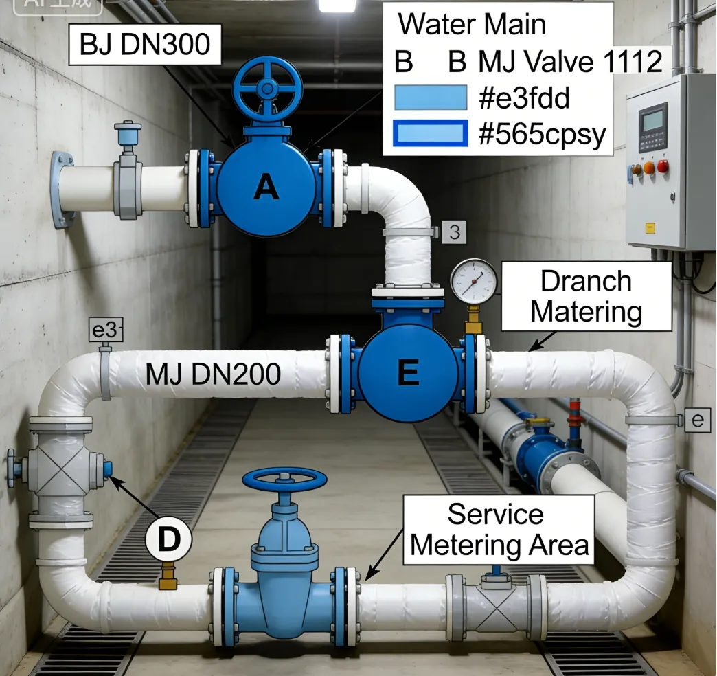
Role, Characteristics, and Application Scenarios of Mechanical Joint Resilient Seated NRS Gate Valves in Pipelines
Functions:
Isolation/on-off control in water distribution
Connection between MJ piping systems
Zone control and isolation
Fire Valve Operational Features:
Mechanical Joint connection - bolts directly to MJ pipe
Resilient seated - bubble-tight seal
Non-rising stem - compact installation
Full port - minimal pressure drop
Typical Applications:
Municipal water distribution networks
Fire protection systems
Industrial water lines
Irrigation systems
Scenario Diagram:
Mechanical Joint Resilient Seated NRS Gate Valves Standards: Materials, Design, and Connections
Material Standards:
Body/Gate: ASTM A536 ductile iron (65-45-12)
Stem: ASTM A276 416 stainless steel
Bolts: ASTM A307 Grade B
Gasket: EPDM per ASTM D2000
Coatings: AWWA C550 epoxy interior
Design Standards:
AWWA C500 or AWWA C509
Pressure: 150psi or 200psi
Face-to-face per AWWA standards
Connection Standards:
Mechanical Joint: AWWA C111 (ANSI/AWWA C111/A21.11)
Dimensions: Per AWWA C110 (ANSI/AWWA C110/A21.10)
MJ Gland: Cast ductile iron
Gasket: MJ push-on type
How to Select Mechanical Joint Resilient Seated NRS Gate Valves
Key Steps:
Specify: Size (DN/NPS), pressure rating, material requirements
Verify Standards: AWWA C500/C509 compliance
Check Certifications: NSF/61 for potable water
Supplier Selection: AWWA-approved manufacturers
Documentation: Request AWWA compliance certificates
Lead Time: Typically 8-12 weeks
Critical Specifications:
Valve size (NPS 3" to 48")
Pressure class (150psi standard)
End type: Mechanical Joint both ends
Material certifications required
AWWA standards compliance
Pre-Shipment Inspection for Export Mechanical Joint Resilient Seated NRS Gate Valves and Key Considerations
Inspection Checklist:
Documentation:
AWWA compliance certificate
Material test reports
NSF/61 certification
Hydrostatic test reports
Physical Inspection:
Dimensional Check:
Face-to-face measurement
MJ bell dimensions
Bolt circle verification
Pressure Testing:
Shell test: 300psi (2×150psi)
Seat test: 165psi (1.1×150psi)
No visible leakage
Visual Inspection:
Casting quality
Coating thickness (8-12 mils)
Proper marking ("MJ", size, pressure)
Operational Test:
Smooth open/close operation
NRS function verified
Export Packaging:
MJ bell protectors (plastic/metal)
VCI bags in valve cavity
Desiccant packs
Wooden crate for protection
Lifting points clearly marked
Key Precautions:
Protect MJ bell ends during transport
Include installation instructions for MJ assembly
Ensure gaskets and bolts are included
Climate-appropriate packaging for destination
Shipping Documents:
Commercial invoice
Packing list
Bill of lading
Certificate of origin
AWWA compliance certificates
Test reports
Material certificates
Mechanical Joint Resilient Seated NRS Gate Valves Size Chart