


Double Sphere Flanged Rubber Expansion Joint KDTF 3
Double Sphere Flanged Rubber Expansion Joint Purepose
Used to connect the water supply and drainage, air pipelines in building, petroleum and chemical etc, industries and able to eliminate the pipeline shock, compensate the pipeline telescopic amount to make installation easier.
Double Sphere Flanged Rubber Expansion Joint Definition and Components
What is a Double Sphere Flanged Rubber Expansion Joint KDTF 3 and its main parts?
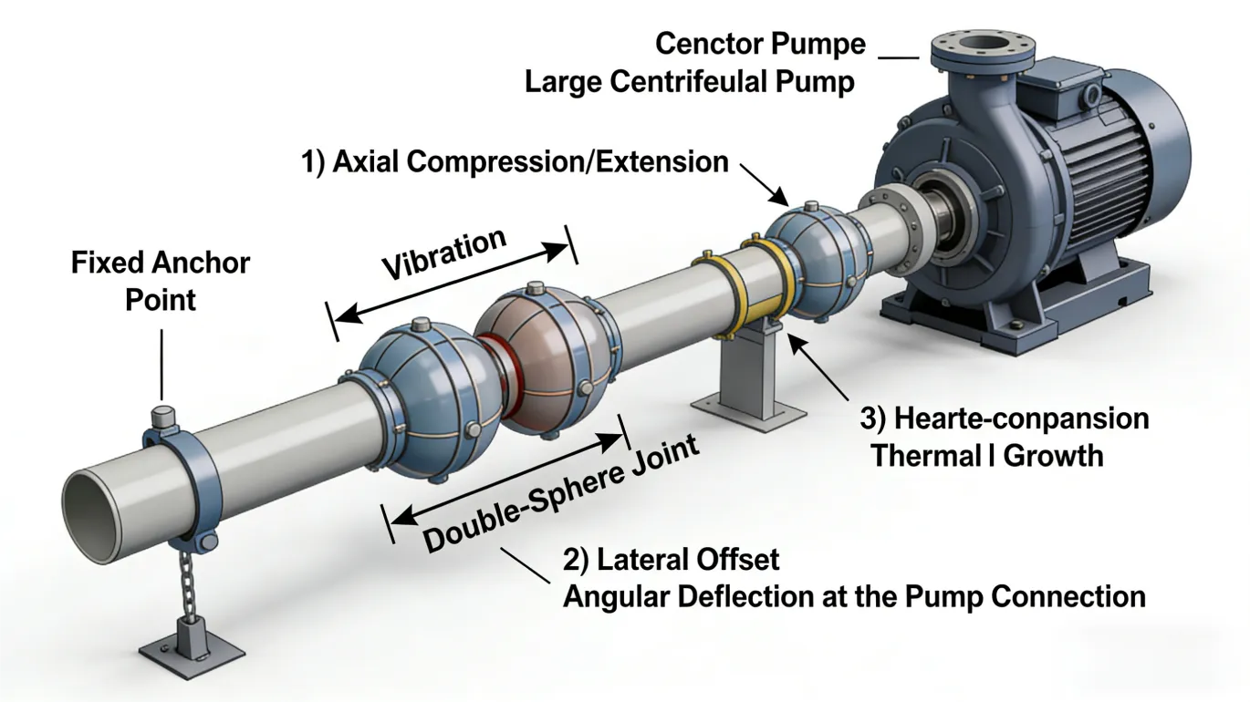
A Double Sphere Flanged Rubber Expansion Joint KDTF 3 is a highly flexible pipeline connector designed to absorb significant multi-directional movement, vibration, and noise. It features two spherical rubber arches (convolutions) connected by a short cylindrical center section, with integral steel flanges at each end. This design provides superior flexibility and movement capacity compared to single-sphere joints, offering a balanced solution for absorbing large displacements.
Double Sphere Flanged Rubber Expansion Joint Main Parts:
- Double Rubber Spheres/Arches: Two identical spherical flexible elements molded from elastomer (e.g., EPDM, NBR). These are the primary components that allow for compression, extension, and lateral movement.
- Center Cylinder (Spool): The short, cylindrical pipe section between the two spheres, which provides stability and defines the joint's neutral length.
- Reinforcement Ply: Multiple layers of high-tensile fabric (like polyester or nylon) or steel cord embedded within each rubber arch, providing pressure containment and preventing over-extension.
- Flanges: Integral, molded steel flanges (typically carbon steel with a corrosion-resistant coating like galvanization) welded or bonded to the ends for bolted connection.
- Inner Liner: A smooth, chemically resistant rubber layer on the inner surface, ensuring fluid compatibility and minimal flow resistance.
- External Cover: A protective rubber layer covering the entire joint, resistant to weathering, ozone, and physical abrasion
Role, Characteristics, and Application Scenarios of Double Sphere Flanged Rubber Expansion Joint in Pipelines
Functions, Operational Features, Usage Scenarios, and Scenario Diagram
Functions: To absorb large axial, lateral, and angular movements; effectively dampen vibration and structure-borne noise; compensate for significant pipeline misalignment; and relieve stress on pumps, turbines, and connected pipework.
Operational Features:
- Enhanced Movement Capacity: The dual-sphere design offers greater axial compression/extension and lateral offset per unit length than single-sphere joints.
- Multi-Directional Absorption: Capable of handling complex movement combinations simultaneously.
- Reduced Spring Force: Provides required flexibility with lower reaction forces transmitted to anchors and equipment compared to a single arch of equivalent movement, due to the longer effective length.
- Vibration Damping: Excellent isolation of high-frequency vibrations from equipment like pumps and compressors.
- Usage Scenarios: Ideal for applications requiring significant movement absorption or superior vibration isolation.
- Central Heating/Cooling Plants: On main supply/return lines to accommodate large thermal expansion.
- Power Station Piping: At turbine inlets/outlets and boiler feed pump connections.
- Large Water & Wastewater Pump Stations: On discharge and suction sides of large pumps.
- Marine Engine Systems: For exhaust and cooling water lines on ships.
- Industrial Process Piping: Connecting to heavy, vibrating machinery like large compressors or crushers.
Double Sphere Flanged Rubber Expansion Joint Standards: Materials, Design, and Connections
Material, Design, and Connection Standards
Water Supply Valve Types Material Standards:
- Elastomer: EPDM (for hot water, steam, weather resistance), NBR (for oils, fuels), Natural Rubber (for general water, high resilience).
- Reinforcement: High-tensile synthetic fabric cord or steel wire cord.
- Flanges & Center Spool: Carbon steel (ASTM A36), often hot-dip galvanized or coated with epoxy paint.
- Design & Performance Standards: Manufactured according to general industry norms and quality standards (e.g., ISO 9001). Performance parameters (pressure rating, movement limits) are typically engineered per manufacturer's specifications, often referencing guidelines from associations like EJMA (Expansion Joint Manufacturers Association).
- Connection Standards: The end flanges conform to standard dimensions for easy integration:
- ASME B16.5 (Class 125 or 150)
- EN 1092-1 (DIN) (PN10 or PN16)
- Specific flange drilling, facing (e.g., Raised Face), and dimensions are per the ordered specification
How to SelectDouble Sphere Flanged Rubber Expansion Joint
- Define Technical Requirements: Specify the necessary parameters: nominal pipe size (DN/NPS), operating pressure and temperature, fluid media (for chemical compatibility), the quantified movements required (axial compression/extension in mm, lateral offset in mm, angular rotation in degrees), and any special conditions (e.g., vacuum, abrasive media).
- Identify and Contact Specialized Manufacturers: Source from reputable manufacturers with expertise in rubber expansion joints for industrial applications. Review their technical catalogs and project history.
- Request a Technical-Commercial Quotation: Submit your requirements. Request a detailed offer including: material specifications for all components, a performance chart with guaranteed movement capacities, dimensional drawings, and available certifications
- Evaluate and Place Order: Compare proposals based on technical accuracy, quality of documentation, price, lead time, and warranty. The purchase order must explicitly state: Model (KDTF 3), Size, Pressure Rating, Elastomer Type, Flange Standard, Movement Requirements, and any special needs (e.g., conductive rubber, limit rods).
Pre-Shipment Inspection for Export Double Sphere Flanged Rubber Expansion Joint and Key Considerations
Pre-Export Inspection and Precautions
Inspection Protocol:
- Visual & Dimensional Check: Inspect for surface flaws, uniformity of the rubber spheres, and integrity of the rubber-to-metal bond. Verify key dimensions (face-to-face length, flange diameters, bolt hole circle) against the approved drawing.
- Material Certification: Review Mill Test Certificates (MTCs) or material statements for the rubber compound, reinforcement, and flange steel.
- Marking Verification: Check for clear, permanent marking with size, pressure rating, model, manufacturer, and elastomer type.
- Packaging Inspection: Ensure the joint is internally braced or mounted on a sturdy wooden skid/pallet to prevent twisting or compression during transit. Flange faces must be protected by covers.
Flexible Rubber Joint Precautions:
- Prevent Deformation: The joint must be shipped and stored in its neutral, unstressed position. It should not be stacked or have heavy items placed on it.
- Protect Critical Surfaces: Use protective covers (wood/plastic) bolted to the flange faces to prevent damage to the sealing surface and bolt holes.
- Environmental Protection: Protect from direct sunlight, ozone sources, extreme temperatures, and oils/greases during storage and shipment.
- Complete Documentation & Marking: Ensure shipping crates are clearly marked with handling instructions ("Flexible - Handle with Care," "Do Not Stack"), identification info, and gross weight. All technical documents (certificates, drawings, manuals) must be sealed in a waterproof envelope and placed inside the shipment.
Double Sphere Flanged Rubber Expansion JointMain dimensions(mm)
| DN | 50 | 65 | 80 | 100 | 125 | 150 | 200 | 250 | 300 | |
| L | 165 | 170 | 175 | 225 | 225 | 225 | 325 | 325 | 325 | |
| D | 165 | 185 | 200 | 220 | 250 | 285 | 340 | 405 | 460 | |
| D1 | 125 | 145 | 160 | 180 | 210 | 240 | 295 | 355 | 410 | |
| b | 15 | 15 | 17 | 18 | 20 | 20 | 20 | 24 | 24 | |
| n-Фd | 4-18 | 4-18 | 8-18 | 8-18 | 8-18 | 8-22 | 12-22 | 12-26 | 12-26 | |
| Axial displacement | Extension | 30 | 30 | 30 | 30 | 35 | 35 | 35 | 35 | 35 |
| Canprassion | 50 | 50 | 50 | 50 | 50 | 50 | 50 | 60 | 60 | |
| Lateral displacement | 19 | 19 | 19 | 24 | 24 | 24 | 26 | 26 | 26 | |
| Deflection angle | 15 | 15 | 15 | 15 | 15 | 15 | 15 | 15 | 15 | |
Note:1. Other specifications and flange standards are available upon request.
- Design and specifications are subject to change without prior notice.